Small-channel parallel pipeline heat exchanger with fins and calculation method

A technology of parallel pipelines and heat exchangers, applied in indirect heat exchangers, heat exchanger types, heat exchange simulation, etc. Heat exchange effect and other issues, to achieve the effect of improving the heat exchange effect outside the tube, making up for the adverse effects, and improving the performance of the heat exchanger

Active Publication Date: 2020-08-21
浙江易斐科技有限公司
View PDF5 Cites 1 Cited by
  • Summary
  • Abstract
  • Description
  • Claims
  • Application Information

AI Technical Summary

Problems solved by technology

The flow direction of the medium outside the heat exchanger tube is generally perpendicular to the windward side of the heat exchanger body to obtain greater heat exchange efficiency. For example, in a heat exchange system including fans, air ducts and heat exchangers, the fans are facing The windward side of the main body of the heat exchanger makes the air carry out forced convection. The wind speed in the middle of the air duct is the largest and the heat exchange effect is the best, but the wind speed at the edge of the air duct is the smallest or almost zero, and the heat exchange effect is obviously poor, which affects the The overall heat transfer effect of the heat exchanger
In addition, according to the different application scenarios of the heat exchanger, the use of the medium in the heat exchanger pipeline is also specific, and this specificity often limits the overall heat exchange effect of the heat exchanger

Method used


Image

  • Small-channel parallel pipeline heat exchanger with fins and calculation method
  • Small-channel parallel pipeline heat exchanger with fins and calculation method
  • Small-channel parallel pipeline heat exchanger with fins and calculation method

Examples


Embodiment Construction

[0026] The present invention will be further elaborated below in conjunction with accompanying drawing:

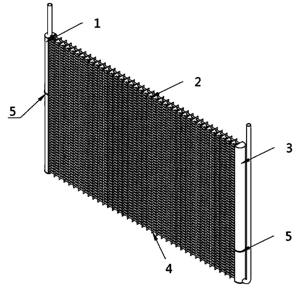
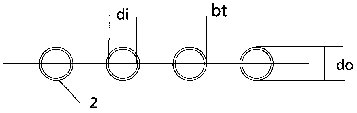
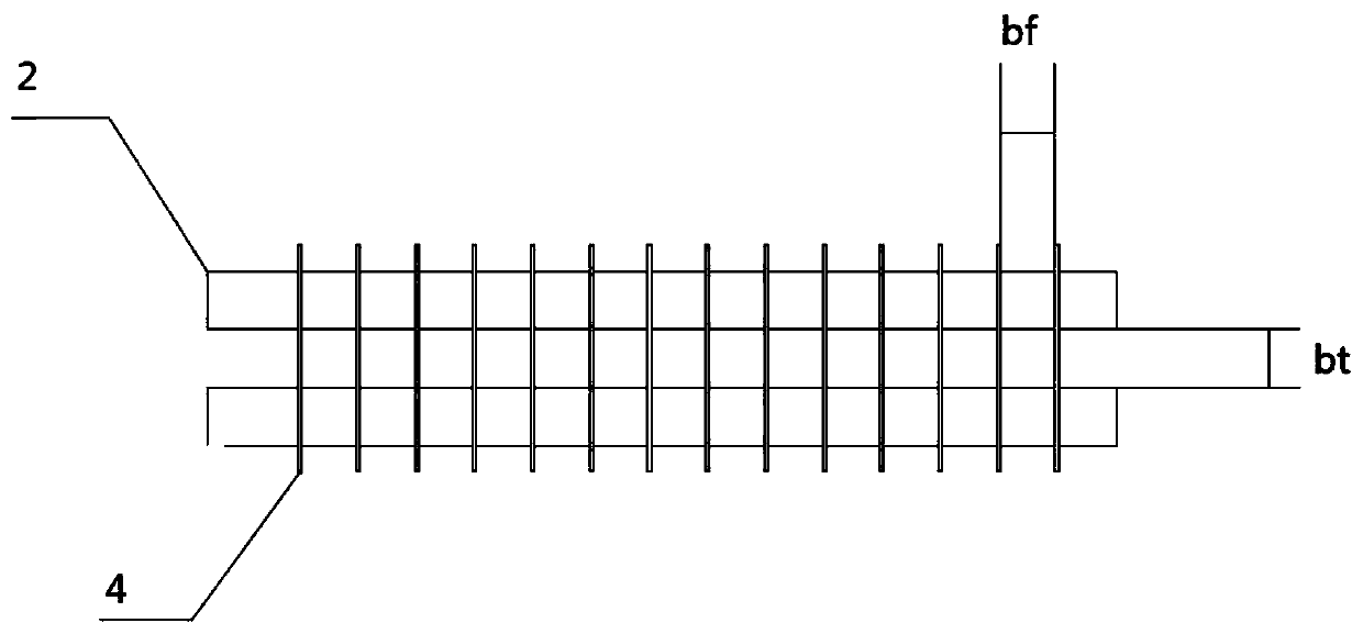
[0027] see Figure 1 to Figure 5 As shown, a finned small channel parallel pipe heat exchanger includes an inlet pipe 1, a parallel pipe 2 and a discharge pipe 3. The parallel pipe 2 communicates with the inlet pipe 1 and the discharge pipe 3 respectively, and the parallel pipe Fins 4 are arranged on the road 2, and the parallel pipes 2 are arranged in at least one row, and when the outer diameter of the parallel pipes 2 is d o The value range is 1mmo ≤3.95mm, the heat transfer capacity of the heat exchanger and the structure of the heat exchanger conform to the following formula:

[0028]

[0029] Among them, Q is the heat transfer, the unit is W; C 0 is the error coefficient, the value is between 0.8 and 1.2; C 1 It is a constant value between 0.023 and 0.027; C 2 is a constant, the value is between 1.2 and 1.4; λ is the thermal conductivity of the medium outside ...


PUM


Abstract

The invention discloses a small-channel parallel pipeline heat exchanger with fins. The heat exchanger comprises an inlet pipe, parallel pipelines and an outlet pipe, wherein the parallel pipelines communicate with the inlet pipe and the outlet pipe correspondingly, the fins are arranged on the parallel pipelines, at least one row of the parallel pipelines are arranged, and when the value range ofthe outer diameter d<o> of the parallel pipelines is that d<o> is larger than 1 mm and smaller than or equal to 3.95 mm, a calculation formula between the heat exchange amount of the heat exchanger and the structure of the heat exchanger is provided. According to the technical scheme, the heat exchanger has the following beneficial effects that the heat exchanger is high in heat exchange efficiency, low in noise and capable of saving energy.

Description

technical field [0001] The invention relates to the field of heat exchangers, in particular to a finned small channel parallel pipeline heat exchanger and a calculation method. Background technique [0002] A heat exchanger is an energy-saving device that transfers heat between two or more media at different temperatures according to the Carnot cycle or reverse Carnot cycle, so the heat exchanger can act as a condenser or an evaporator. Among them, the condenser refers to using the medium outside the heat exchanger to cool the medium in the heat exchanger, so that the medium outside the heat exchanger absorbs the heat of the medium in the heat exchanger and the temperature rises. If the medium is a phase change substance, When the temperature is constant, energy storage is realized; the evaporator refers to the use of the medium outside the heat exchanger to heat the medium in the heat exchanger, so that the medium outside the heat exchanger absorbs the cooling capacity of t...

Claims


Application Information

Patent Timeline
Patent Type & Authority Applications(China)
IPC IPC(8): F28D1/053F28F1/32F25B39/00G06F17/18
CPCF25B39/00F28D1/05333F28F1/32F28F2200/00G06F17/18
Inventor 郑时红赵云鹏茅新波
Owner 浙江易斐科技有限公司
Why Eureka
Try Eureka