Rapid positioning detection method and device for automobile headlamp

A positioning detection device and the technology of automobile headlights, which are applied in the field of positioning detection of automobile headlights, can solve the problems of positioning failure, limited light receiving area, and headlight position deviation, etc., and achieve the effect of fast positioning and reduced moving range

Active Publication Date: 2020-08-21
成都成保发展股份有限公司
View PDF12 Cites 9 Cited by
  • Summary
  • Abstract
  • Description
  • Claims
  • Application Information

AI Technical Summary

Problems solved by technology

Although this method solves the shortcomings of the manual headlight detector, it cannot determine the approximate position of the headlight because the vehicle enters from different positions, so the detector body is required to judge the strongest light area, because the detector The light-receiving area of ​​the main body is limited, and it is necessary to move the light box back and forth several times in the horizontal direction and move up and down in the vertical direction to track and locate the strongest light area. Therefore, the software processes a large amount of data, takes a long time to detect, and often misses the light intensity. The highest position, resulting in positioning failure
[0004] At the same time, when the vehicle is driving in, the vehicle body is usually not straightened, causing the position of the headlights to deviate, which seriously affects the detection results

Method used


Image

  • Rapid positioning detection method and device for automobile headlamp
  • Rapid positioning detection method and device for automobile headlamp
  • Rapid positioning detection method and device for automobile headlamp

Examples


Embodiment Construction

[0047] The technical solution of the present invention will be further described in detail below in conjunction with the accompanying drawings, but the protection scope of the present invention is not limited to the following description.

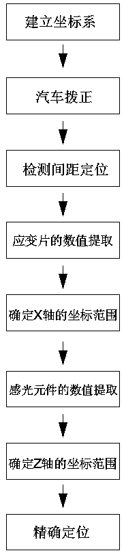
[0048] Such as Figure 1 to Figure 12 Shown, a kind of rapid location detection method of automobile headlamp, comprises the following steps:

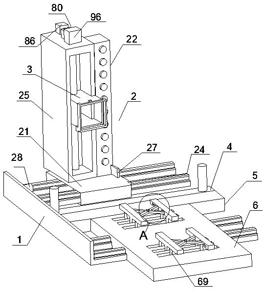
[0049] S1, set the coordinate system, the positioning plate 1 is set as the zero point position of the coordinate system, the X-axis guide rail 24 is set as the X-axis, and the Z-axis pillar 25 is set as the Z-axis;

[0050] S2, adjust the orientation of the automobile straightening assembly 6 according to the orientation of the automobile, so that the automobile is driven into the automobile straightening assembly 6, and the automobile is adjusted by the automobile straightening assembly 6;

[0051] S3. After the car is straightened, drive the car to the sensing component 4. When the front end of ...


PUM


Abstract

The invention discloses a rapid positioning detection method and device for an automobile headlamp. The rapid positioning detection device comprises a positioning plate, a transmission assembly, a headlamp detector, an induction assembly, a horizontal positioning assembly and an automobile correcting assembly. The transmission assembly comprises a sliding base, a supporting column, a first photosensitive assembly and a shaft guide rail assembly. An X-axis guide rail assembly is fixed on one side of the positioning plate; the sliding base is arranged on the X-axis guide rail assembly in a sliding manner; the supporting column is vertically fixed to the sliding base, a Z-axis guide rail is vertically arranged on one side of the supporting column, the headlamp detector is arranged on the Z-axis guide rail in a sliding mode, the first photosensitive assembly is arranged at the front end of the supporting column, and the induction assembly, the horizontal positioning assembly and the automobile correcting assembly are sequentially arranged in front of the transmission assembly. The approximate range of the headlamp on the X axis and the approximate range of the headlamp on the Z axis are determined through the horizontal positioning assembly and the first photosensitive assembly respectively, so that the moving range of the headlamp detector is greatly reduced, and positioning of the headlamp is faster.

Description

technical field [0001] The invention relates to the field of positioning and detection of automobile headlights, in particular to a method and device for rapid positioning and detection of automobile headlights. Background technique [0002] The vehicle headlight tester is used to detect the luminous intensity and optical axis offset of the car headlights. It is suitable for motor vehicle inspection stations, automobile manufacturers, auto repair shops, supporting 4S shops, and agricultural machinery supervision departments for tractors and automobiles. Check and adjust the headlights. In recent years, various types of vehicle headlight detectors have appeared on the market. As a detector, whether the test results can accurately reflect the actual beam intensity of vehicle headlights is a difficult point. The main factors are: when testing vehicles For headlights, the center of the detector body should be facing the strongest beam area of ​​the current vehicle headlights. ...

Claims


Application Information

Patent Timeline
Patent Type & Authority Applications(China)
IPC IPC(8): G01M11/06
CPCG01M11/061G01M11/067
Inventor 宋新民陶雪松
Owner 成都成保发展股份有限公司
Why Eureka
Try Eureka