[0025] In order to enable those skilled in the art to better understand the technical solutions of the present invention, the present invention will be further described in detail below in conjunction with the accompanying drawings and specific embodiments.
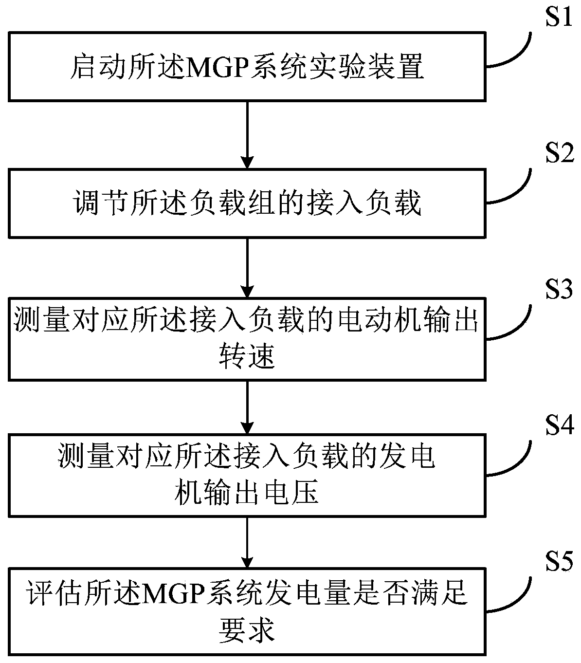
[0026] like figure 1 As shown, the proposed MGP system power generation evaluation method of the present invention mainly includes the following steps:
[0027] S1, start the MGP system experimental device;
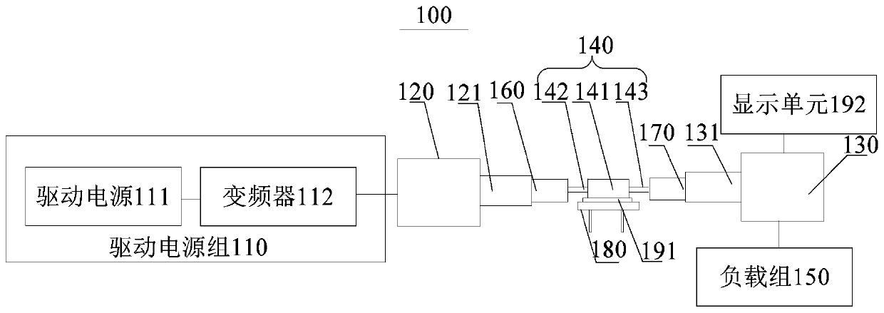
[0028] The MGP system experimental device involved in the present invention is as figure 2 As shown, an experimental device 100 for an MGP system includes a drive power pack 110 , a motor 120 , a generator 130 , a rotational speed measuring instrument 140 and a load pack 150 . The drive power group 110 is connected to the power terminal of the motor 120, the output shaft 121 of the motor 120 is connected to the input shaft 131 of the generator 130, and the load group 150 is connected to the load of the generator 130. The speed measuring instrument 140 is located between the motor 120 and the generator 130 and is connected to the motor 120 and the generator 130 respectively to measure the output speed of the motor 120 .
[0029] Specifically, such as figure 2 As shown, when using the experimental device with the structure of this embodiment to conduct experiments, the power supply pack is driven to drive the motor 120 to rotate, and the motor 120 transmits the output torque to the generator 130, thereby driving the generator 130 to rotate together. During the rotation of the generator 130 , according to the connected load group 150 , the different output speeds of the motor 120 and the different output voltages output by the generator 130 , the power generation performance of the generator 130 can be studied.
[0030] The MGP system experimental device of this embodiment can study the power generation performance of the generator in the MGP system when it is connected to a load group and at different output speeds, so that the power generation performance curve of the generator can be obtained. In this way, when the MGP system is connected to the power grid, according to the work load of the power grid and the output speed of the motor, the power generation in the MGP system can be effectively predicted, so that it can be determined whether the power generation meets the work load requirements.
[0031] S2. Adjust the access load of the load group;
[0032] The load group 150 may include, for example, multiple loads with different resistance values, and the generator 130 is selectively connected to the multiple loads with different resistance values.
[0033] The MGP system experimental device of this embodiment can effectively simulate the power generation performance of the generator under different work loads by setting multiple loads with different resistance values, so as to more effectively predict whether the power generation in the MGP system meets the work load requirements .
[0034] In some optional implementations, the load group 150 includes at least one variable load with adjustable resistance. Exemplarily, the variable load can be a sliding rheostat, or the variable load can also be a virtual Loaded to the generator in a programmed way, that is, the variable load is a programmable load.
[0035] S3. Measuring the output speed of the motor corresponding to the connected load;
[0036] The MGP system experimental device of the present invention includes a rotational speed measuring instrument 140, and the rotational speed measuring instrument 140 is located between the motor 120 and the generator 130, and is connected to the motor 120 and the generator 130 respectively to measure The output speed of the electric motor 120.
[0037] It should be noted that there is no limitation on the specific structure of the speed measuring instrument. For example, the speed measuring instrument may use a photoelectric speed measuring instrument, or the speed measuring instrument may also use a Hall element speed measuring instrument, a centrifugal speed measuring instrument, etc. , can be determined according to actual needs, which is not limited in this embodiment.
[0038] S4. Measuring the motor output voltage corresponding to the connected load;
[0039] During the rotation of the generator 130 , according to the different output speeds of the connected load group 150 and the motor 120 , the different output voltages output by the generator 130 are measured.
[0040] The output voltage detection device may adopt common voltage detection devices in the field.
[0041] S5. Evaluate whether the power generation of the MGP system meets the requirements;
[0042] The output power of the motor can be calculated according to the output speed of the detected motor; the output power of the motor is the input power of the generator; the output power of the generator can be calculated according to the output voltage of the generator 130 detected and the load connected; comparison If the loss of the output power of the motor and the output power of the generator is within the normal range, such as less than 50%, it is considered that the power generation of the MGP system meets the requirements.
[0043] Further, a storage unit can also be set in the MGP system to pre-store the ratio of the output power of the generator to the input power of the generator. For example, if the ratio is greater than 0.5, it is deemed to meet the power generation requirement.
[0044] like figure 2 As shown, the MGP system experimental device 100 also includes a first coupling 160, and the rotational speed measuring instrument 140 includes a measuring body 141 and a first connecting shaft 142 extending from the measuring body 141 to the direction of the motor 120 , the first end of the first coupling 160 is connected with the output shaft 121 of the motor 120 , and the second end of the first coupling 160 is connected with the first connecting shaft 142 .
[0045]In the MGP system experimental device of this embodiment, the motor and the speed measuring instrument are connected by the first shaft coupling. The structure is simple, and the output torque of the motor can be effectively transmitted, so that the output torque measured by the speed measuring instrument can Accurate speed.
[0046] like figure 2 As shown, the MGP system experimental device 100 also includes a second coupling 170, and the rotational speed measuring instrument 140 also includes a second connecting shaft 143 extending from the measuring body 141 to the direction of the generator 130, so A first end of the second coupling 170 is connected to the input shaft 131 of the generator 130 , and a second end of the second coupling 170 is connected to the second connecting shaft 143 .
[0047] The MGP system experimental device of this embodiment connects the generator and the rotational speed measuring instrument through the second coupling, has a simple structure, and can effectively transmit the output torque of the motor to realize the synchronous rotation of the generator and the motor , and can also make the output speed measured by the speed measuring instrument accurate.
[0048] like figure 2 As shown, in order to effectively support the rotational speed measuring instrument 140, the MGP system experimental device 100 also includes a bracket 180, the bracket 180 is arranged under the measurement body 141 to support the measurement body 141, and the first connection The shaft 142 and the second connecting shaft 143 are symmetrically arranged on two sides of the bracket 180 .
[0049] like figure 1 As shown, in order to effectively slow down the impact on the speed measuring instrument 140 and the support 180 caused by the high-speed operation of the motor 120, the MGP system experimental device 100 also includes at least one buffer piece 191, and the buffer piece 191 is sandwiched between the measurement Between the body 141 and the bracket 180 , for example, the buffer member 191 may be a buffer elastic member, such as a buffer spring or buffer rubber.
[0050] like figure 2 As shown, the drive power set 110 includes a drive power 111 and a frequency converter 112 , and the drive power 111 is connected to the power terminal of the motor 120 through the frequency converter 112 .
[0051] In some optional implementation manners, the load group 150 may include multiple loads with different resistance values, and the generator 130 is selectively connected to the multiple loads with different resistance values.
[0052] The MGP system experimental device of this embodiment can effectively simulate the power generation performance of the generator under different work loads by setting multiple loads with different resistance values, so as to more effectively predict whether the power generation in the MGP system meets the work load requirements .
[0053] like figure 2 As shown, the MGP system experimental device 100 also includes a display unit 192, the display unit 192 is connected to the output terminal of the rotational speed measuring instrument 140 and the generator 130 to display the output rotational speed and the generator 130 output voltage. Exemplarily, the display unit 192 may use an oscilloscope.
[0054] The MGP system experimental device of this embodiment can intuitively display the output voltage of the generator under different loads and different output speeds with the help of the display unit, so as to more effectively predict whether the power generation in the MGP system meets the workload requirements .
[0055] It can be understood that, the above embodiments are only exemplary embodiments adopted for illustrating the principle of the present invention, but the present invention is not limited thereto. For those skilled in the art, various modifications and improvements can be made without departing from the spirit and essence of the present invention, and these modifications and improvements are also regarded as the protection scope of the present invention.