Inhalation component generating device, control circuit, and control method and control program of inhalation component generating device

a technology of inhalation component and generating device, which is applied in the direction of process and machine control, instruments, tobacco, etc., can solve the problem of reducing the accuracy of determination of small residual amount state, and achieve the effect of increasing resistance and reducing capacity

Active Publication Date: 2020-04-09
JAPAN TOBACCO INC
View PDF10 Cites 3 Cited by
  • Summary
  • Abstract
  • Description
  • Claims
  • Application Information

AI Technical Summary

Benefits of technology

[0011]The term “load” means a component which consumes energy in an electric circuit, and is especially used in this application to indicate a component for mainly generating an inhalation component. In the load, a heating means such as a heat generator is included, and for example, an electric resistance heat generator, an induction heating (IH) means, and so on can be included. Also, a means for generating an inhalation component by an ultrasonic wave, a means for generating an inhalation component by a piezoelectric element, an atomizer, and so on can be included. In the case where the load is referred to as being a “load group”, besides a load for generating an inhalation component, other components such as an element for producing light, sound, vibration, or the like can be included in the load group. In the case where a communication module and so on are provided, they can be included in the load group. Meanwhile, a microcomputer and so on in an electric circuit are strictly elements which obtain energy by applying a very small current; however, in this application, it is assumed that they are not included in the load group.
[0012]The term “aerosol” means a dispersion of fine liquid or solid particles in the air. With respect to a “deterioration diagnosis function”, in general, examples of battery deterioration include a decrease in capacity and an increase in resistance. The deterioration diagnosis function may be, for example, a function of acquiring the voltage value of the power supply for diagnosis of a decrease in capacity, and determining whether the acquired value is equal to or larger than the lower limit value of a predetermined reference range.

Problems solved by technology

Since the voltage value of the battery derived as described above is likely to be deviated from the true value, as a result, there is a problem that the accuracy of determination of the small residual amount state decreases.

Method used


Image

  • Inhalation component generating device, control circuit, and control method and control program of inhalation component generating device
  • Inhalation component generating device, control circuit, and control method and control program of inhalation component generating device
  • Inhalation component generating device, control circuit, and control method and control program of inhalation component generating device

Examples


Embodiment Construction

[0038]An embodiment of the present invention will be described below with reference to the drawings. However, specific structures and electric circuits to be described below are merely examples of the present invention, and the present invention is not necessarily limited to them. Also, hereinafter, structural parts basically having the same function will be described with the same reference symbol or reference symbols corresponding to each other; however, for ease of explanation, sometimes the reference symbols will be omitted. Although the configurations of some parts of a device are different between a certain drawing and other drawings, it should be noted that they are not essential differences in the present invention and every configuration can be used.

[0039]1. Configuration of Device

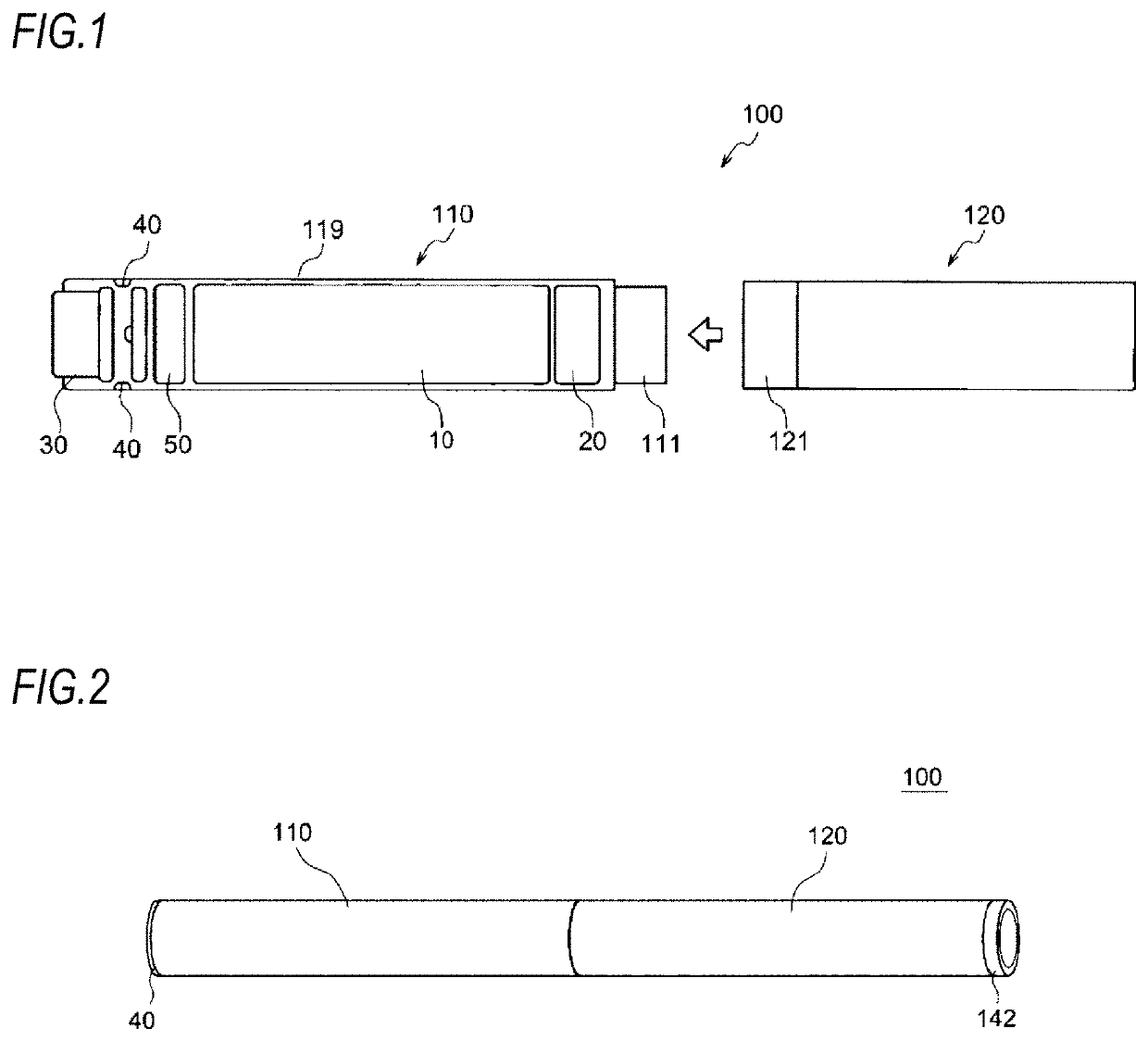
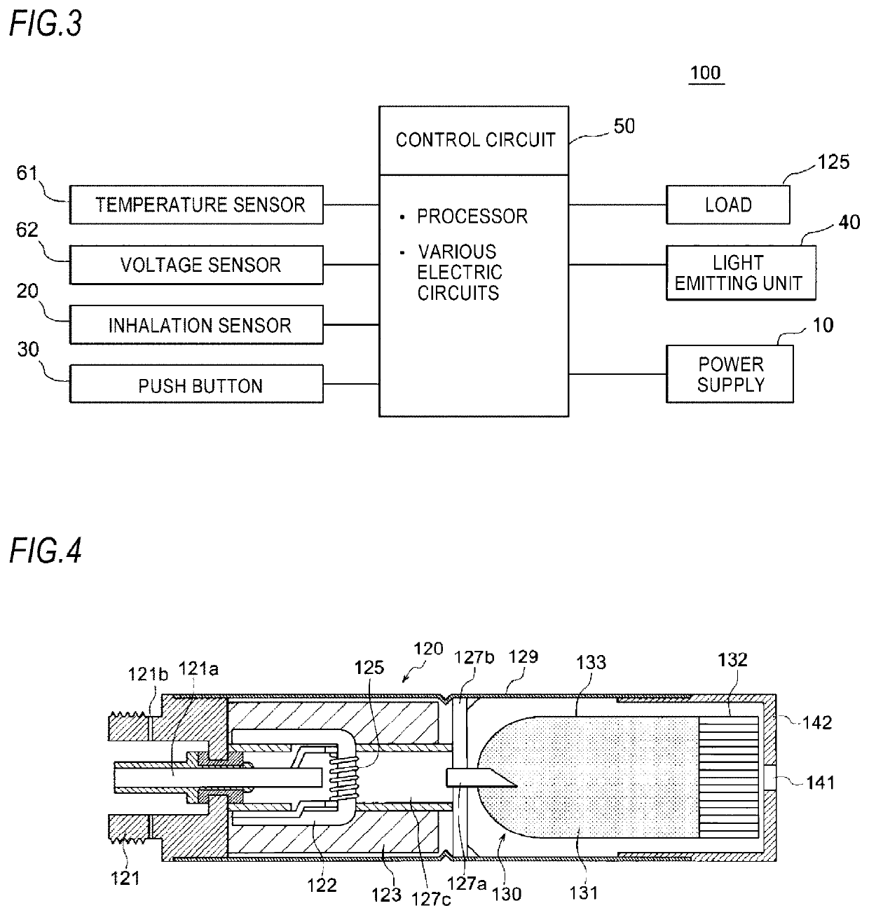
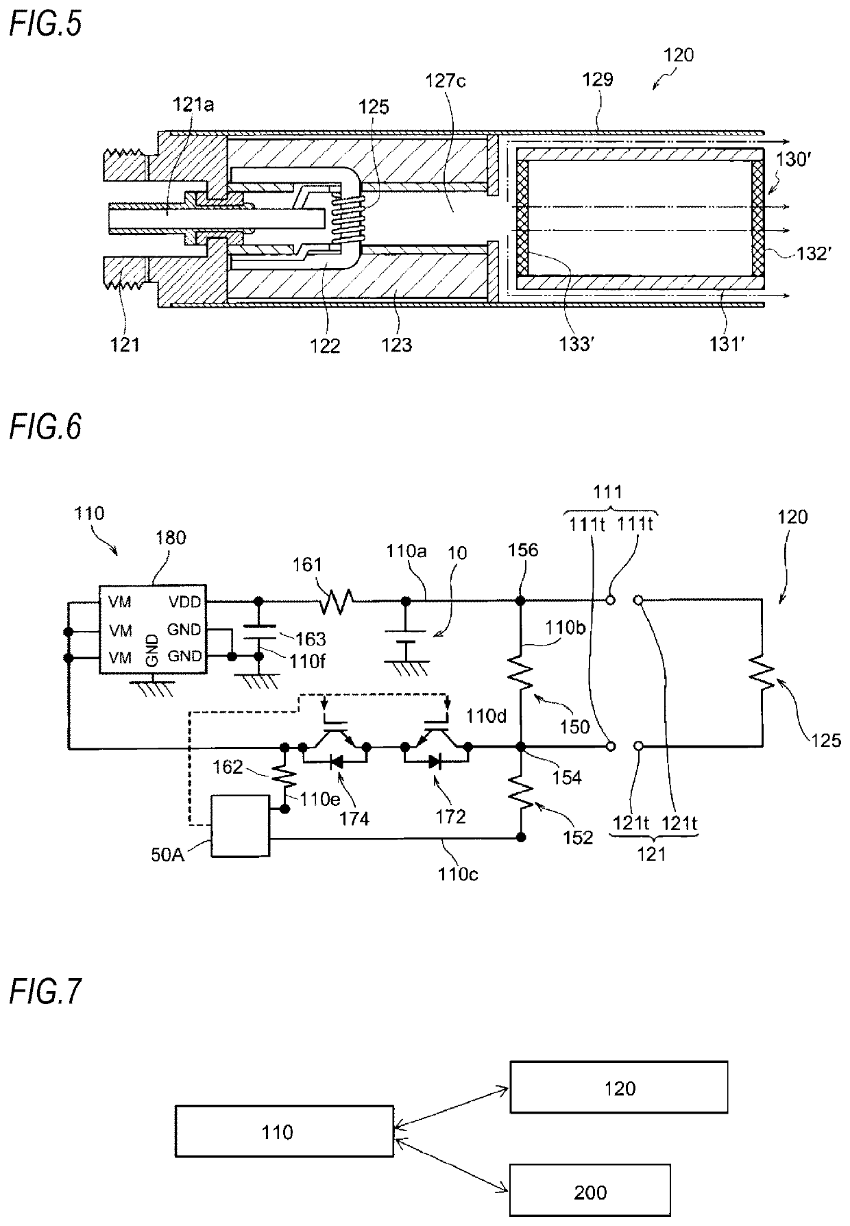
[0040]An inhalation component generating device 100 of the present embodiment includes a power supply unit 110, and a cartridge unit 120 configured to be attachable to and detachable from the powe...


PUM


Abstract

An inhalation component generating device includes: a power supply; a load group including a load configured to evaporate or atomize an inhalation component source by power from the power supply; and a control circuit configured to be able to acquire a voltage value of the power supply. The control circuit performs: a process (a1) of acquiring a closed circuit voltage value of the power supply in a closed circuit state in which the power supply and the load group are electrically connected; and a process (a2) of comparing the acquired closed circuit voltage value and a first reference voltage value, and determining that the power supply is in a small residual amount state in a case where the closed circuit voltage value is smaller than or is equal to or smaller than the reference voltage value.

Description

CROSS-REFERENCE TO RELATED APPLICATIONS[0001]This application is based upon and claims the benefit of priority from prior Japanese patent application No. 2018-189496, filed on Oct. 4, 2018, the entire contents of which are incorporated herein by reference.TECHNICAL FIELD[0002]The present invention relates to an inhalation component generating device, a control circuit, and a control method and a control program of the inhalation component generating device, and particularly, to an inhalation component generating device, a control circuit, and a control method and a control program of the inhalation component generating device capable of successfully performing determination of a small residual amount state.BACKGROUND ART[0003]Recently, instead of traditional cigarettes, inhalation component generating devices for generating an inhalation component by evaporating or atomizing a flavor source such as tobacco or an aerosol source have been proposed. Such an inhalation component generat...

Claims


Application Information

Patent Timeline
Patent Type & Authority Applications(United States)
IPC IPC(8): A24F47/00H02M3/158
CPCA24F47/008H02M3/158A24F47/00H01M10/48H02J7/00A24F40/53A24F40/10H05B1/02H05B6/02H02J7/0063G01R19/16576G01R31/382A24F40/50A24F40/465A24F40/60A24F40/51
Inventor AKAO, TAKESHIYAMADA, MANABUFUJITA, HAJIME
Owner JAPAN TOBACCO INC
Why Eureka
Try Eureka