
LED driving chip, backlight unit, display panel and display device

A LED driver and chip technology, applied to static indicators, instruments, etc., can solve the problems of brightness difference, complex driving structure, and shortened scanning time

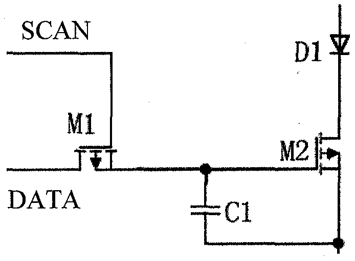
Pending Publication Date: 2020-08-21
BEIJING XIANXIN TECH CO LTD
View PDF0 Cites 4 Cited by
  • Summary
  • Abstract
  • Description
  • Claims
  • Application Information

AI Technical Summary

Problems solved by technology

However, with the improvement of display resolution, the scanning time of each line per unit time is shortened, especially when it is applied to a large-size display device, it is difficult to realize the PM backlight method.
In order to solve the above problems, the display device can be divided into several regions for driving. The driving structure of this method is relatively complicated, and there are brightness differences between the divided regions.

Method used


Image

  • LED driving chip, backlight unit, display panel and display device
  • LED driving chip, backlight unit, display panel and display device
  • LED driving chip, backlight unit, display panel and display device

Examples


Embodiment Construction

[0042] In order to make the purpose, technical solutions and advantages of the embodiments of the present invention clearer, the technical solutions in the embodiments of the present invention will be clearly and completely described below in conjunction with the drawings in the embodiments of the present invention. Obviously, the described embodiments It is a part of embodiments of the present invention, but not all embodiments. Based on the embodiments of the present invention, all other embodiments obtained by those skilled in the art without creative efforts fall within the protection scope of the present invention.

[0043]In the description of the present invention, it should be noted that the terms "center", "upper", "lower", "left", "right", "vertical", "horizontal", "inner", "outer" etc. The indicated orientation or positional relationship is based on the orientation or positional relationship shown in the drawings, and is only for the convenience of describing the pr...


PUM


Abstract

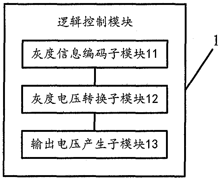
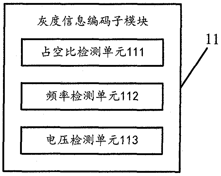
The invention discloses an LED driving chip, a backlight unit, a display panel and a display device. The LED driving chip is connected with an LED, is used for controlling the LED, and comprises a logic control module which is used for receiving a first analog data signal shared by one row or one column of the position where the LED is located and converting the first analog data signal into a second analog data signal for independently controlling the LED. The logic control module comprises a gray scale information coding sub-module which is used for coding a first analog data signal to generate a digital gray scale signal; a gray-scale voltage conversion sub-module which is connected with the gray-scale information coding sub-module and is used for generating a digital output signal according to the digital gray-scale signal; and an output voltage generation sub-module which is connected with the gray-scale voltage conversion sub-module and is used for generating a second analog datasignal according to the digital output signal. The LED driving chip is used for independently controlling the LED, so that a plurality of different AM backlight driving modes are realized, and the control of the LED is more accurate and flexible.

Description

technical field [0001] The invention relates to the field of display technology, in particular to an LED driver chip, a backlight unit, a display panel and a display device. Background technique [0002] At present, the backlight methods of display devices can be roughly divided into two types, one type is passive matrix (Passive Matrix, abbreviated as PM) backlight, and the other type is active matrix (abbreviated as AM) backlight. Way. [0003] The cost of the PM backlight method is relatively low, and it is easy to implement technically. However, with the improvement of display resolution, the scanning time of each line per unit time is shortened, especially when it is applied to a large-size display device, it is difficult to realize the PM backlight method. In order to solve the above problems, the display device can be divided into several regions for driving. The driving structure of this method is relatively complicated, and there are brightness differences among t...

Claims


Application Information

Patent Timeline
IPC IPC(8): G09G3/34
CPCG09G3/3413
Inventor 林荣镇严丞辉任虎男
Owner BEIJING XIANXIN TECH CO LTD
Learn More