

Aircraft, flight system, and structure inspection system
A technology of aircraft and rotation axis, which is applied in the field of aircraft and can solve problems such as aircraft attitude or trajectory interference
- Summary
- Abstract
- Description
- Claims
- Application Information
AI Technical Summary
Problems solved by technology
Method used
Image

Examples
Embodiment 1
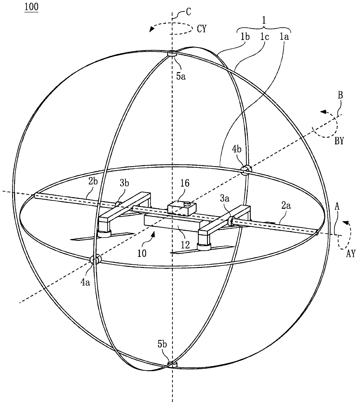
[0037] First, the configuration of the aircraft according to Embodiment 1 is described. figure 1 is a perspective view schematically illustrating a configuration example of an aircraft 100 (for example, a drone). Such as figure 1 As shown, the aircraft 100 includes an outer frame 1 , brackets 2 a and 2 b , first joints 3 a and 3 b , second joints 4 a and 4 b , third joints 5 a and 5 b , and a multi-rotor helicopter 10 . The outer frame 1 includes a first rotating frame 1a, a second rotating frame 1b and a third rotating frame 1c.
[0038] The brackets 2a and 2b are fixed to the first rotating frame 1a. The brackets 2a and 2b are connected to the multirotor helicopter 10 via first joints 3a and 3b, respectively. The first joints 3a and 3b are made of usual mechanical parts such as ball bearings or sliding bearings and allow continuous rotation of the connected parts. The same applies to the second joints 4a and 4b and the third joints 5a and 5b.
[0039] Using the first jo...
Embodiment 2
[0116] Next, an aircraft according to Embodiment 2 will be described. The same codes are assigned to the same elements as in the first embodiment described above, and their descriptions are omitted.
[0117] In this embodiment, the power supply unit is connected to a plurality of storage batteries. In addition, the position of the center of gravity of each storage battery is located below the A-axis in the direction of gravity, and is not on the C-axis. Figure 9 Shown is an example of the configuration of the multirotor helicopter 10a of the aircraft 100 according to the present embodiment.
[0118] exist Figure 9 Among them, the multi-rotor helicopter 10a includes a control unit 12a and batteries 17a and 17b. Unlike the control unit 12 according to Embodiment 1, the control unit 12a includes the controller 200 but does not include a power supply unit.
[0119] The storage batteries 17a and 17b together serve as a power supply unit. The center of gravity 21a of the stor...
Embodiment 3
[0124] The aircraft according to Embodiment 3 is described below. The same symbols are assigned to the same elements as those in Embodiments 1 and 2 described above, and thus descriptions thereof are omitted.
[0125] In this embodiment, the outer frame of the aircraft includes at least one of the mesh dome structure and the fullerene structure.
[0126] The grid dome structure is a regular dodecahedron, which is a regular polyhedron close to a sphere, a regular icosahedron or a truncated icosahedron of a semi-regular polyhedron, subdivided into triangles close to equilateral triangles, while keeping it as symmetrical as possible, The sphere is constructed from geodesic lines or groups of line segments each approximating a geodetic line. In particular, the mesh dome structure is a dome structure assembled from many of the same structural materials mentioned above arranged side by side.
[0127] The fullerene structure is a dome structure of a truncated icosahedron composed o...
PUM
 Abstract
Description
Claims
Application Information