
Method for track position improvement by means of a track-movable track-tamping machine

A track position, tamping machine technology, applied in the direction of track, track maintenance, roads, etc., to avoid systematic errors, long durability, and high track position quality.

Inactive Publication Date: 2020-08-21
HP3 REAL GMBH
View PDF11 Cites 2 Cited by
  • Summary
  • Abstract
  • Description
  • Claims
  • Application Information

AI Technical Summary

Problems solved by technology

But because there is about 10-15m between the working position and the measuring and checking position, it is no longer possible to affect the already processed track in between

Method used


Image

  • Method for track position improvement by means of a track-movable track-tamping machine
  • Method for track position improvement by means of a track-movable track-tamping machine
  • Method for track position improvement by means of a track-movable track-tamping machine

Examples


Embodiment Construction

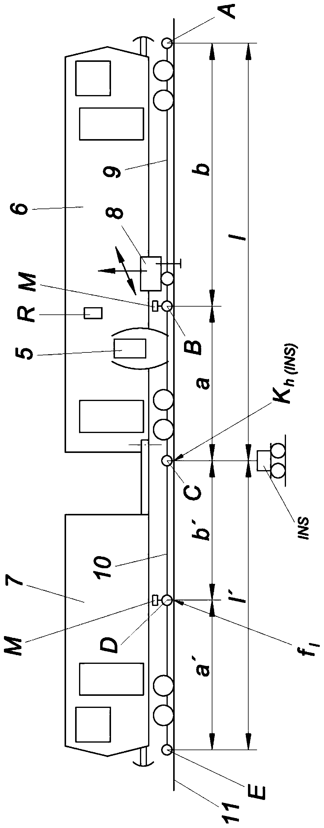
[0028] figure 1A rail tamping machine for carrying out the method according to the invention is shown. A trailer 7 is connected to the track tamping machine 6 . The track tamping machine 6 is equipped with a tamping unit 5 . The rail 11 is lifted and aligned by the lifting and correcting unit 8 into the target rail position which needs to be corrected with respect to its position in the gravel bed. Below the rail tamping machine 6 there is a three-point working measuring system with three measuring carriages A, B, C and strings 9 , for example steel strings, stretched between the measuring carriages. In the measuring cart B, the sensor M measures the heightwise and lateral deflection of the string 9 . The chord 9 has a length l and is divided into chord sections a and b, between which the measuring carriage B is arranged.

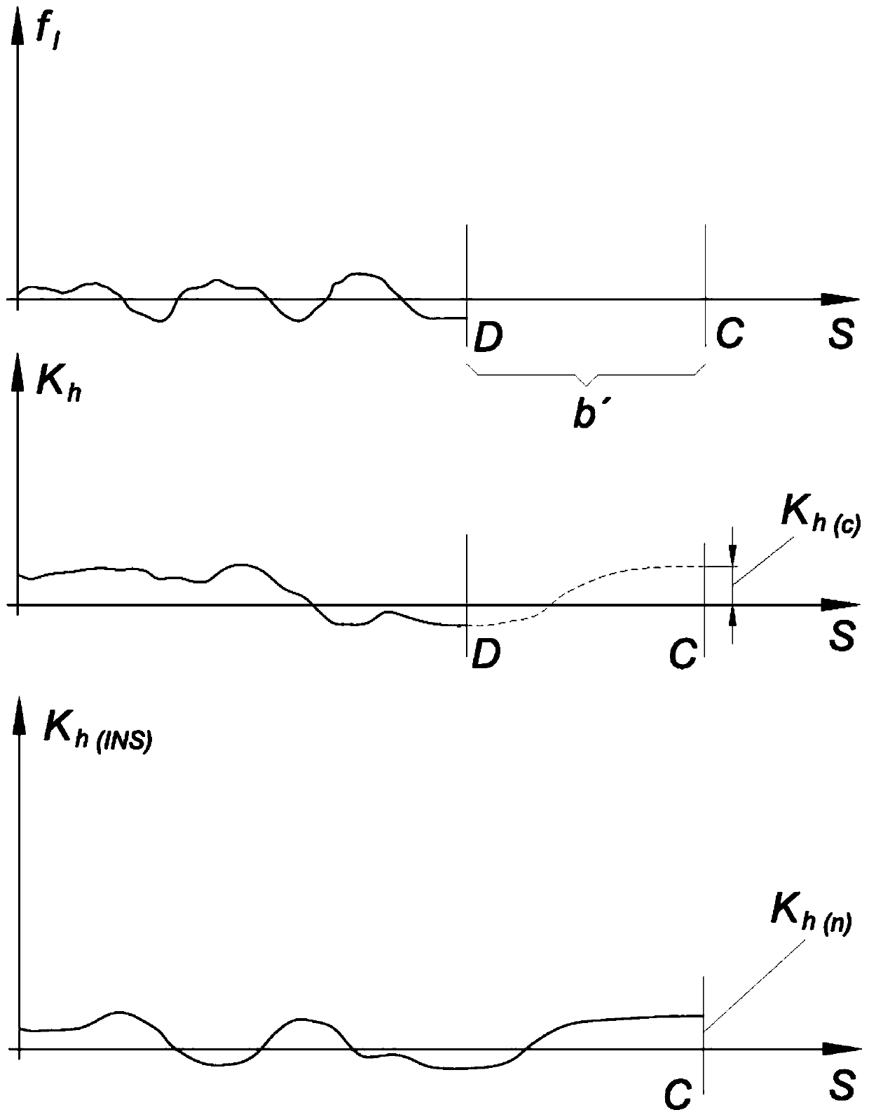
[0029] To verify the measurement, a test string 10 can be stretched between the measuring carriages E and C on the trailer 7 . In the measuring carria...


PUM


Abstract

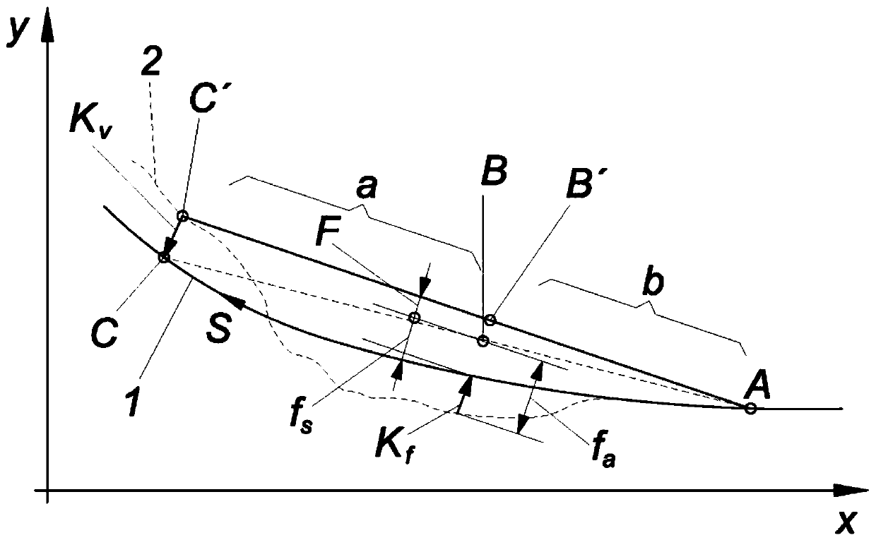
A method for track position improvement by means of a track-movable track-tamping machine (6) with a three-point working measurement system, which has three measurement carriages (A, B, C), a cord (9)stretched therebetween, a tamping unit (5), a lifting / straightening assembly (8) for tracks and an odometer particularly. The position of the track after the correction work of the track-tamping machine (6) is recorded by the measurement system, wherein a computer (R) calculates the difference between a predetermined desired track position (1) and an actual position recorded by the measurement system, that is to say a residual error (Kh), and the position of the rear cord end at the rear measurement carriage (C) of the track-tamping machine (6) of the three-point working measurement system iscontinuously corrected in such a way that the rear cord end at the measurement carriage (C) is guided on the desired track position (1).

Description

technical field [0001] The present invention relates to a method for improving a three-point method for improving track position by a track tamping machine. Background technique [0002] Most tracks used in railways are designed as ballasted tracks. Here, the sleepers are in the crushed stone ballast. The wheel forces acting by the train running on it cause irregular settlements in the crushed stone ballast and shifts in the lateral positional geometry of the track. Due to the settlement in the gravel bed, errors occur in the longitudinal height, superelevation (in curves) and correction points. If these geometric parameters exceed certain comfort or safety limit values, maintenance work is carried out. Track tamping machines improve track geometry that has deteriorated due to train loads. For this purpose, the rail is lifted into the desired rail position by means of an electrohydraulically controlled lifting correction device and fixed in this position by compacting (t...

Claims


Application Information

Patent Timeline
Patent Type & Authority Applications(China)
IPC IPC(8): E01B35/00E01B27/20E01B27/17B61K9/08
CPCE01B27/17E01B35/06E01B35/08E01B35/10B61K9/08E01B35/00G01B5/14
Inventor B.利赫特伯格
Owner HP3 REAL GMBH
Learn More