Spoon dyeing device
A dyeing device and spoon technology, which is applied to the device and coating of the surface coating liquid, can solve the problems of inability to uniformly control the dyeing time, time-consuming and labor-intensive problems, and achieve the effect of reducing manual operations and facilitating collection and removal
- Summary
- Abstract
- Description
- Claims
- Application Information
AI Technical Summary
Problems solved by technology
Method used
Image
Examples
Embodiment 1
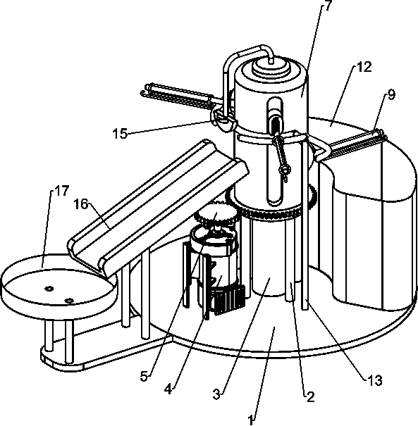
[0020] A spoon dyeing device such as Figure 1-3 As shown, it includes a frame 1, a support frame 2, a column 3, a dye box 12, a power assembly and a support assembly, a support frame 2 and a column 3 are welded in the middle of the top of the frame 1, and the column 3 is located in the support frame 2, and the frame 1 upper right side is placed with dyestuff box 12, frame 1 upper part is provided with the power unit that is powered by the motor rotation to carry out work, and the power unit is slidingly provided with support unit.
[0021] Such as figure 1 and 2 As shown, the power assembly includes a reduction motor 4, a gear 5, a ring gear 6 and a rotating sleeve 7, the left side of the upper part of the frame 1 is fixed with a reduction motor 4 through bolts, and the output shaft of the reduction motor 4 is connected with a The gear 5 and the upper part of the support frame 2 are rotatably provided with a rotating sleeve 7, and the cylinder 3 is located in the rotating s...
Embodiment 2
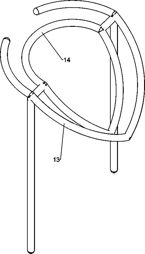
[0027] On the basis of Example 1, such as figure 1 and 4 As shown, it also includes a first adjusting rod 13 and a second adjusting rod 14 , the top of the frame 1 is welded with the first adjusting rod 13 , and the inner side of the first adjusting rod 13 is welded with the second adjusting rod 14 .
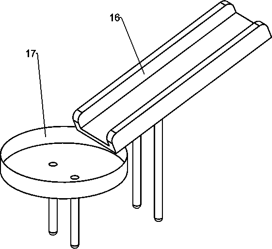
[0028] Such as figure 1 and 5 As shown, block 15, slide 16 and collection box 17 are also included, block 15 is welded on the left side of column 3 top, slide 16 is welded on left side of frame 1 top, and collection box 17 is welded on left side of frame 1 top .
[0029] The working principle of the above-mentioned embodiment: when the support assembly moves, the slider 8 is close to the second adjustment rod 14, and moves up and down along with the second adjustment rod 14, so that the swing rod 9 drives the spoon to enter from the top of the dye box 12 Dye box 12, and leaves from above after dyeing is finished, prevents that dyestuff is flowed out along the side wall of dy...
PUM
 Abstract
Description
Claims
Application Information
 - R&D
- Intellectual Property
- Life Sciences
- Materials
- Tech Scout
- Unparalleled Data Quality
- Higher Quality Content
- 60% Fewer Hallucinations
Browse by: Latest US Patents, China's latest patents, Technical Efficacy Thesaurus, Application Domain, Technology Topic, Popular Technical Reports.
© 2025 PatSnap. All rights reserved.Legal|Privacy policy|Modern Slavery Act Transparency Statement|Sitemap|About US| Contact US: help@patsnap.com


