
I beam burring device capable of being suitable for different specifications

An I-beam and deburring technology, which is applied to machine tools, automatic grinding control devices, and manufacturing tools suitable for grinding the edge of workpieces, etc., can solve the problem of uneven grinding surface, size differences, and lack of matching performance, etc. problems, to achieve the effect of ensuring work accuracy and stability

Inactive Publication Date: 2020-08-25
陈烁
View PDF7 Cites 12 Cited by
  • Summary
  • Abstract
  • Description
  • Claims
  • Application Information

AI Technical Summary

Problems solved by technology

Traditionally, in the deburring process of I-beam steel parts, manual hand-held grinding equipment is usually used to grind and remove burrs from the steel parts, but the deburring efficiency is low, and the grinding surface is uneven; and the processed I-beam steel Due to the difference in the size of the parts, it does not have good matching and applicable performance when grinding and removing burrs through mechanical automation equipment

Method used


Image

  • I beam burring device capable of being suitable for different specifications
  • I beam burring device capable of being suitable for different specifications
  • I beam burring device capable of being suitable for different specifications

Examples


Embodiment Construction

[0026] The following will clearly and completely describe the technical solutions in the embodiments of the present invention with reference to the accompanying drawings in the embodiments of the present invention. Obviously, the described embodiments are only some, not all, embodiments of the present invention. Based on the embodiments of the present invention, all other embodiments obtained by persons of ordinary skill in the art without making creative efforts belong to the protection scope of the present invention.

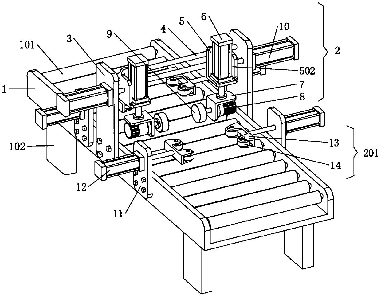
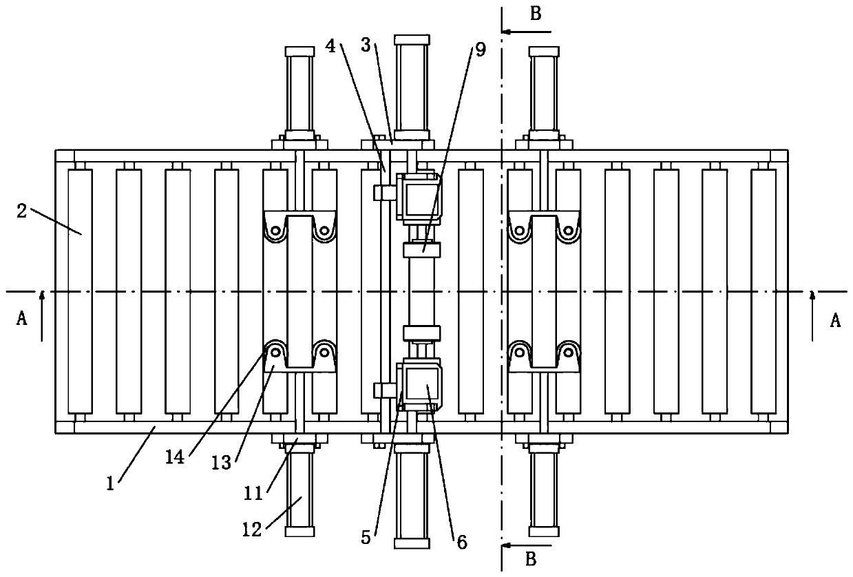
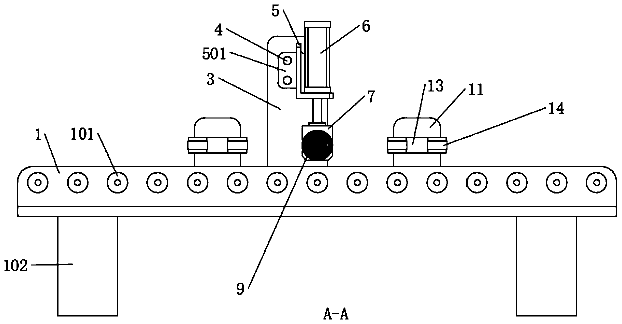
[0027] The present invention provides such Figure 1-4 The illustrated I-beam deburring device applicable to different specifications includes a machine table 1, a grinding device 2 and a guide device 201, combined with figure 1 , image 3 and Figure 4 As shown, the bottom of the machine platform 1 is welded with a support foot 102, and the machine platform 1 is provided with a roller table 101, and the roller table 101 is arranged to transport the I-beam. ...


PUM


Abstract

The invention discloses an I beam burring device capable of being suitable for different specifications and relates to the field of burring devices. The I beam burring device capable of being suitablefor different specifications comprises a machine table, a polishing device and guiding devices. A roller bed is arranged in the machine table, the polishing device is arranged on the machine table, and the guiding devices are arranged on two sides of the polishing device. By controlling a telescopic rod of a transverse shifting driven hydraulic cylinder to stretch, two lifting hydraulic cylinderblocks are adjusted to move in an axial direction of a sliding shaft till two millstones are in contact with the side wall of an I beam. By driving the millstones by a polishing motor, the side wall of the I beam is polished to burr. Meanwhile, by controlling the telescopic rod of a lifting hydraulic cylinder to stretch, the millstones lift up and down, so that it is convenient to polish and burrthe side wall of the I beam comprehensively and effectively.

Description

technical field [0001] The invention relates to the field of deburring devices, in particular to an I-beam deburring device applicable to different specifications. Background technique [0002] During the production and casting process of I-beam steel parts, some burrs will remain on the surface of the workpiece. Traditionally, in the deburring process of I-beam steel parts, manual hand-held grinding equipment is usually used to grind and remove burrs from the steel parts, but the deburring efficiency is low, and the grinding surface is uneven; and the processed I-beam steel Due to the size difference of the parts, when the burrs are removed by mechanical automation equipment, it does not have good matching performance. Contents of the invention [0003] The object of the present invention is to provide an I-beam deburring device applicable to different specifications, so as to solve the problems raised in the above-mentioned background technology. [0004] In order to a...

Claims


Application Information

Patent Timeline
Patent Type & Authority Applications(China)
IPC IPC(8): B24B9/04B24B41/00B24B41/02B24B49/04B24B51/00
CPCB24B9/04B24B41/005B24B41/02B24B49/045B24B51/00
Inventor 陈烁
Owner 陈烁
Learn More