
High-rigidity high-speed maglev turnout supporting point arrangement structure and arrangement method

A technology with supporting points and high rigidity, applied in the directions of roads, tracks, buildings, etc., can solve the problems of low rigidity and easy resonance of turnout beams, and achieve the effect of improving comfort and safety, improving resonance problems and strong flexibility.

Pending Publication Date: 2020-08-25
CHINA RAILWAY BAOJI BRIDGE GRP
View PDF1 Cites 2 Cited by
  • Summary
  • Abstract
  • Description
  • Claims
  • Application Information

AI Technical Summary

Problems solved by technology

[0005] Design purpose: To avoid the deficiencies in the background technology, to design a support point layout structure and layout method for high-rigidity high-speed maglev turnouts that not only solve the related problems of low stiffness of the turnout beam and easy resonance, but also meet the high-speed maglev system with a speed of 600Km per hour

Method used


Image

  • High-rigidity high-speed maglev turnout supporting point arrangement structure and arrangement method

Examples


Embodiment 1

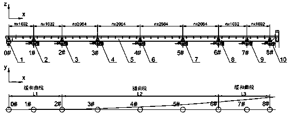
[0023] Embodiment 1: with reference to attached figure 1 and 2 . An arrangement of support points for high-speed maglev turnouts with large stiffness, which consists of straight lines, transitional curves, circular curves, transitional curves and straight lines to form uninterrupted high-speed maglev turnouts, and the connection points between the straight lines, transitional curves, circular curves, transitional curves and straight lines are Linear conversion point, the linear conversion point is the supporting point of the driving trolley.

[0024] The uninterrupted connection point between the transitional curve and the circular curve is the 2# driving trolley, the uninterrupted connection point between the circular curve and the transitional curve is the 6# driving trolley, and the uninterrupted connection point between the transitional curve and the straight line is the 8# driving trolley .

[0025] Arrange one or more supporting trolleys between 2#, 6#, and 8# adjacen...

Embodiment 2

[0030]Embodiment 2: On the basis of Embodiment 1, a method for arranging support points of large-rigidity high-speed maglev turnouts, the key trolley arrangement position: according to the line shape requirements of straight line-transition curve-circle curve-transition curve straight line switch, it is divided into 5 points The plane combination composed of segment functions is used to fit the bending curve of the turnout steel girder. The turnout girder must reach the deformation curve composed of the transitional curve-circular curve-transitional curve under the drive of concentrated load; set up four trolley support points, Among them, 0#, 2#, 6#, and 8# trolleys are placed on the linear conversion points to ensure that the linearity of the turnout beam meets the curve requirements after the four support points are in place; the layout of the supporting trolleys: the layout position of the supporting trolleys needs to be considered The position of the stator and functional ...


PUM


Abstract

The invention relates to a high-rigidity high-speed maglev turnout supporting point arrangement structure and an arrangement method, which solves related problems of low rigidity, easy resonance and the like of a turnout beam and can also meet a requirement of a high-speed maglev system with a speed of 600Km per hour. A straight line, a relaxation curve, a circular curve, the relaxation curve andthe straight line form an uninterrupted high-speed maglev turnout, connecting points among the straight line, the relaxation curve, the circular curve, the relaxation curve and the straight line are linear conversion points, and the linear conversion points are supporting points of a driving trolley. The structure and the method have advantages that large-rigidity high-speed maglev turnout supporting point arrangement is provided, vertical rigidity and transverse rigidity of the turnout are calculated, analyzed and optimized through a finite element method, and a use requirement for large rigidity is met. According to the arrangement method, the rigidity of the turnout beam is greatly improved, linear precision of the turnout after switch is improved, and the problem of resonance caused bythe low rigidity of the turnout is solved.

Description

technical field [0001] The invention relates to a large rigidity high-speed maglev turnout support point arrangement structure and an arrangement method which not only solve the related problems such as low stiffness of turnout beams and easy resonance, but also satisfy the high-speed maglev system with a speed of 600Km per hour, and belong to the technical field of urban rail transit. Background technique [0002] At present, the stiffness design value of the high-speed maglev turnout on the Shanghai Line is based on the German high-speed maglev specification. The design value of the vertical stiffness under the train load is L / 4800, and the lateral stiffness is L / 15000, but it cannot meet the 600km / h high-speed maglev train. Requirements for stiffness values ​​and transverse stiffness values. [0003] CN 101007538 B. The name "switching device for magnetic levitation vehicles", which includes: a beam that can be bent transversely to the direction of travel and provided wit...

Claims


Application Information

Patent Timeline
Patent Type & Authority Applications(China)
IPC IPC(8): E01B25/30E01B25/34
CPCE01B25/30E01B25/34
Inventor 李利军牛均宽余锋吉敏廷张宁
Owner CHINA RAILWAY BAOJI BRIDGE GRP
Learn More