
Road safety deceleration strip device

A technology of deceleration device and deceleration belt, which is applied in the direction of roads, roads, road signs, etc., can solve the problems of discomfort of people in the car, vehicle suspension burden, bumps, etc., and achieve the effect of reducing bumps, simple structure, and reasonable design

Inactive Publication Date: 2020-08-25
韩建杰
View PDF8 Cites 0 Cited by
  • Summary
  • Abstract
  • Description
  • Claims
  • Application Information

AI Technical Summary

Problems solved by technology

[0003] While the existing deceleration belt serves the purpose of deceleration, it also causes great bumps to many low-speed motor vehicles, causing discomfort to the occupants in the vehicle, and burdening the suspension of the vehicle.

Method used


Image

  • Road safety deceleration strip device
  • Road safety deceleration strip device
  • Road safety deceleration strip device

Examples


Embodiment Construction

[0017] The present invention will be further described below in conjunction with the drawings and specific embodiments:

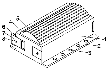
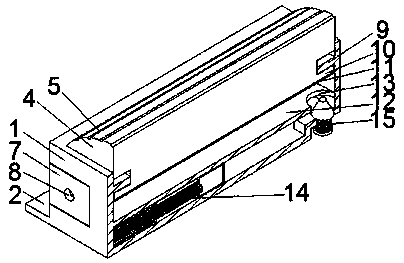
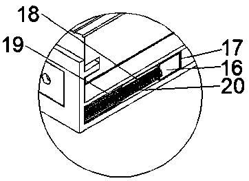
[0018] Such as Figure 1-5 As shown, a road safety deceleration belt device includes a device housing 1, a side fixing plate 2, an expansion bolt 3, an arc lifting deceleration device 4, a strip anti-skid pattern 5, a sliding groove 6, a sliding plate 7, a screw hole 8, The fixing plate 9 and the I-shaped lifting plate 10 are integrally formed with side fixing plates 2 on the left and right sides of the bottom of the device housing 1, and five expansion bolts 3 are installed on each side fixing plate 2. The device housing The top of the body 1 is equipped with an arc-shaped lifting and decelerating device 4, the top of the arc-shaped lifting and decelerating device 4 is equidistantly provided with strip-shaped anti-skid lines 5, and the device housing 1 is provided with slide grooves 6 on the front and rear ends of the device. Sliders 7 are installed in the s...


PUM


Abstract

The invention discloses a road safety deceleration strip device. Side fixing plates are integrally formed on the left and right sides of the bottom of the device shell. Five expansion bolts are mounted on the side fixing plate on each side; an arc-shaped lifting speed reducing device is mounted at the top of the device shell; strip-shaped anti-skid lines are formed at equal intervals in the top ofthe arc-shaped lifting speed reducing device; sliding grooves are formed in the side edges of the front end and the rear end of the device shell. Sliding blocks are installed in the sliding grooves correspondingly; screw holes used for connection are formed in the sliding blocks correspondingly; fixing plates are integrally formed at the two ends of the inner side of the top of the device shell correspondingly; an I-shaped lifting plate is integrally formed at the bottom of the arc-shaped lifting speed reducing device; and the I-shaped lifting plate is installed in the fixing plates at the two ends. The device is simple in structure and reasonable in design, the height of the speed reducer is automatically adjusted when an internal liquid penetrates through the through holes; when the vehicle speed is high, the speed reducer cannot descend in time so as to achieve the purpose of speed reduction; and when the vehicle speed is low, the speed reducer descends to reduce jolt.

Description

Technical field [0001] The invention relates to a road safety deceleration belt device. Background technique [0002] Speed ​​bumps are also called deceleration ridges, which are traffic facilities installed on highways to slow passing vehicles. The shape is generally striped, but also somewhat shaped; the material is mainly rubber, but also metal; it is usually yellow and black to attract visual attention, and the road is slightly arched to achieve the purpose of vehicle deceleration. It is generally set at road crossings, industrial and mining enterprises, schools, residential communities and other road sections where vehicles need to slow down and road sections that are prone to traffic accidents. It is a new type of traffic-specific safety setting used to reduce the speed of motorized and non-motorized vehicles. [0003] While the existing deceleration belts serve the purpose of deceleration, they also cause great turbulence to many low-speed motor vehicles, cause discomfort t...

Claims


Application Information

Patent Timeline
IPC IPC(8): E01F9/529
CPCE01F9/529
Inventor 韩建杰马文霞王宏陶文超
Owner 韩建杰
Learn More