Hinge for glass doors

A technology of hinges and hinges, which is applied to hinges with pins, applications, household appliances, etc., to achieve the effects of simple connection, simplified assembly and adjustment, and long working life

Inactive Publication Date: 2020-08-25
邹智深
View PDF5 Cites 0 Cited by
  • Summary
  • Abstract
  • Description
  • Claims
  • Application Information

AI Technical Summary

Problems solved by technology

Replacing springs or other joints may...

Method used


Image

  • Hinge for glass doors
  • Hinge for glass doors
  • Hinge for glass doors

Examples


Embodiment Construction

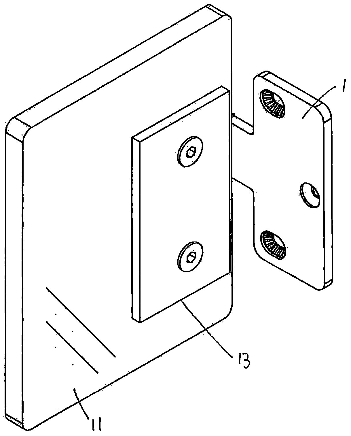
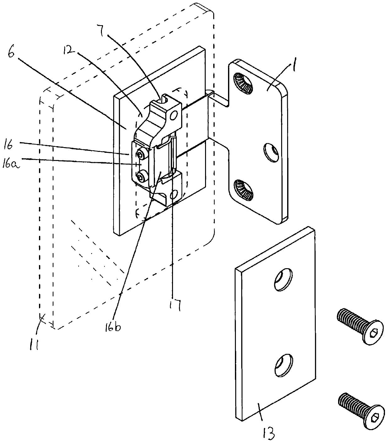
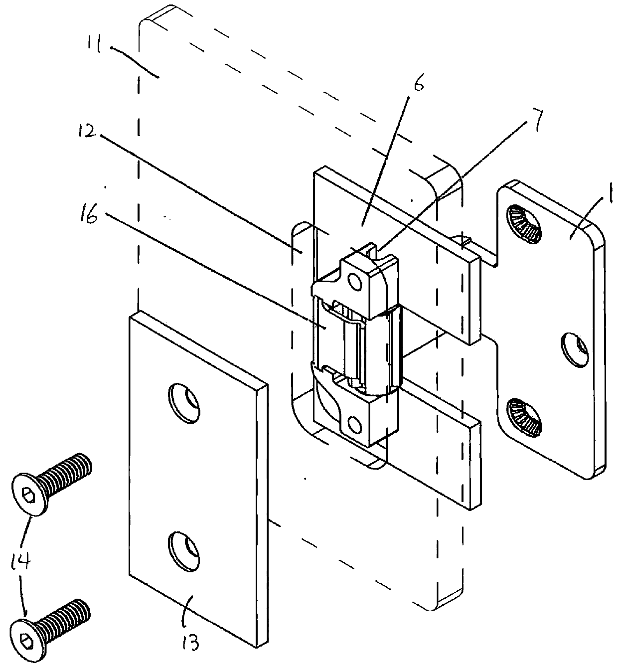
[0085] Figures 1 to 6 The hinge shown includes a mounting which may be a mounting plate 1 and which may be provided with fixings such as holes into which bolts or screws may be inserted to secure the mounting plate to a door frame, wall or other structure. In alternative embodiments, the mount may include clamping means for adjacent door panels. Arm 2 extends perpendicularly from mounting plate 1 . The first end of the arm 2 is fixed on the mounting plate. The second end of the arm 2 is integral with a collar 3 having an axial hole 4 in which a hinge shaft or pin 5 is rotatably received such that the shaft or pin 5 lies on the hinge axis 5a.

[0086] The hinge body 6 has upper and lower housings with an eye 7 arranged to receive a pin or the end of the shaft 5 so that the hinge body 6 can pivot relative to the mounting plate 1 .

[0087] The collar 3 is part-cylindrical with axial bores 4 arranged along the collar axis. The collar 3 comprises a pair of engaging formations...


PUM


Abstract

A hinge comprises a mounting piece and a hinge body; an arm connected to the mounting piece at the first end; a collar connected to the second end of the arm and having an axial hole; a rotating shaftarranged at the axis of the hinge and rotatably mounted in the hole of the collar. The hinge body includes blades including one or more shells, the shells accommodating the rotating shaft and allowing the blades to rotate around the axis. The radial outer surface of the collar or the rotating shaft includes one or more engagement structures orientated corresponding to one or more angles of the hinge axis. The blades include an engagement member movable between an engagement position and a release position. Compared with the release position, the engagement position is closer to the hinge axis, and the engagement member is biased to the engagement position. Engagement of the engagement member and the engagement structures will enable the hinge to be oriented to the blades in a certain angle, thus applying motion resistance to the hinge to generate a stop position where the free motion of the hinge is stopped.

Description

technical field [0001] The present invention relates to a hinge for mounting a glass door, for example a shower door or a door for a sauna or steam room. The present invention relates particularly, but not exclusively, to a door that can be held in an open position to provide force against closing, eg by contact with a user or in windy conditions. This is usually done using a door stop, such as a wedge or weight. Background technique [0002] Many hinges for shower doors or other glass doors require a piston to interact with the shaft and the closing spring. If the manufacturing dimensions are out of tolerance, noise may be generated during operation. If the compression spring breaks, a skilled technician will be required to disassemble the part in order to install a replacement. In alternative cases, the closing force may be insufficient. For example, depending on the size of the door, or if the environment is windy, a greater or lesser closing force may be required. R...

Claims


Application Information

Patent Timeline
IPC IPC(8): E05D3/02E05D5/02E06B7/23E05D7/04E05D11/10
CPCE05D3/02E05D5/02E05D5/0246E05D7/04E05D11/1028E05Y2900/132E06B7/23A47K3/36A47K2003/367E05D11/105E05D2007/0469E05D2011/1035E05Y2201/48E05Y2900/114A47K3/30E05D11/10
Inventor 邹智深邹忠余绍恩
Owner 邹智深
Why Eureka
Try Eureka