
Intelligent lamp integrating multiple functions

A multi-functional and intelligent technology, applied in energy-saving control technology, components of lighting devices, semiconductor devices of light-emitting components, etc., can solve problems such as affecting fire-fighting vehicles, affecting drivers, easily causing traffic jams, etc. The effect of protecting the safety of drivers and pedestrians and reducing the impact

Pending Publication Date: 2020-08-25
浙江瑞林光环境集团有限公司
View PDF6 Cites 0 Cited by
  • Summary
  • Abstract
  • Description
  • Claims
  • Application Information

AI Technical Summary

Problems solved by technology

[0003] The prior art application number is 201821436036.4, an intelligent street lamp device based on the Internet of Things. Its structure includes a plurality of street lamps erected on both sides of the road and a geomagnetic sensor box installed in the road. The interior of the box is provided with a control circuit board and a street lamp control switch, the control circuit board is connected with the street lamp control switch, an infrared sensor is also provided on the light pole of the street lamp, a solar panel is provided on the top of the street lamp, and the solar The battery board is connected to the light bulb of the street lamp through the street lamp control switch, and a geomagnetic sensor is provided inside the geomagnetic sensor box; a communication module is provided on the control circuit board, and the communication module is connected to a cloud server. The fault tolerance rate of monitoring the vehicles on the road ensures the accuracy of monitoring, so as to realize the reasonable control of the opening of street lights, but the content of the scene used by this invention is not perfect, for example, in the middle of the night, although the traffic flow is not large, it will still happen. There are a small number of pedestrians, and the speed of the vehicle at night is generally high. If the pedestrians have not triggered the trigger device of the comparative patent, the light generated by the street lamp is not strong enough to cause the driver's vision to be poor, which will affect the driver's judgment and mistakenly think that there is no one in front. After waiting to drive, even if the pedestrian triggers the switch to remind the driver at this time, it is easy to cause traffic accidents
[0004] The prior art application number is 201320587849.4, which is a fire monitor installed on a street light pole. Its structure includes a casing, an electronic circuit board installed in the casing, and an input keyboard arranged in the casing and used to input the number of the installed street light pole. , the shell is provided with a fire alarm sending button and a fire alarm cancel button, and the electronic circuit board is provided with a data processor, and after pressing the fire alarm sending button, the number of the installed street light pole is synchronously transmitted to the data transmitter of the host monitoring host and communicates with the The power supply module connected to the data processor, the fire alarm unit controlled by the data processor is installed on the shell, and the power supply control switch controlled by the data processor is connected in series in the power supply circuit of the fire alarm unit. Clearly point out the specific location of the fire for the firefighters, and visually indicate the passing pedestrians and firefighting vehicles through the sound and light alarm device. How close it is, it is too late to realize that the vehicle is close to the accident site, and it is still easy to cause traffic jams and affect the entry of firefighting vehicles

Method used


Image

  • Intelligent lamp integrating multiple functions
  • Intelligent lamp integrating multiple functions
  • Intelligent lamp integrating multiple functions

Examples


Embodiment Construction

[0029] In order to make the technical means, creative features, goals and effects achieved by the present invention easy to understand, the present invention will be further described below in conjunction with specific embodiments.

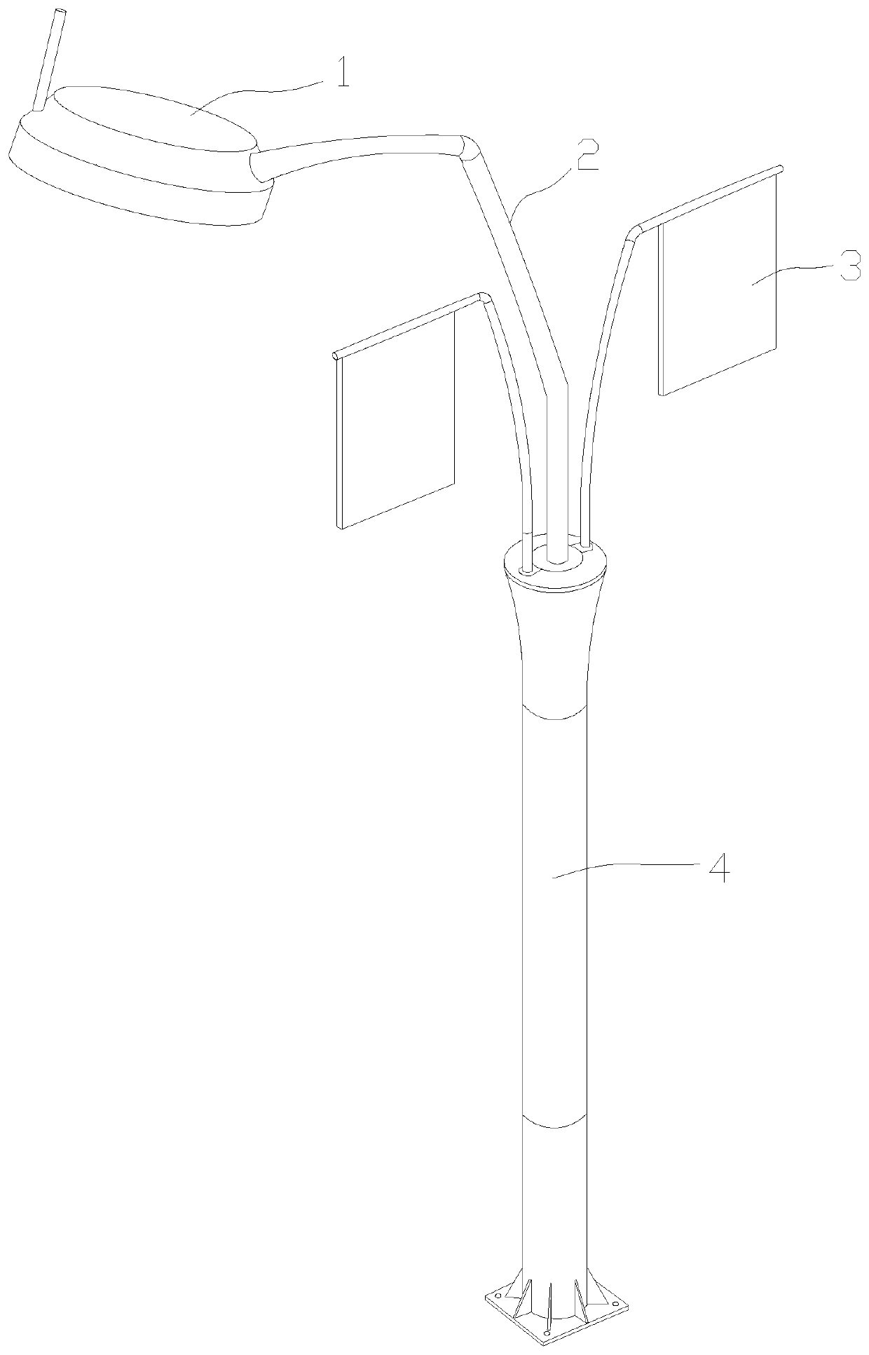
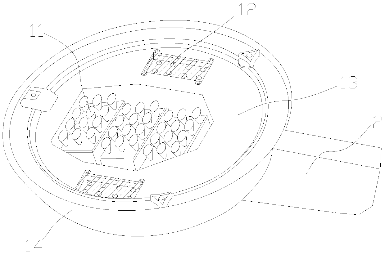
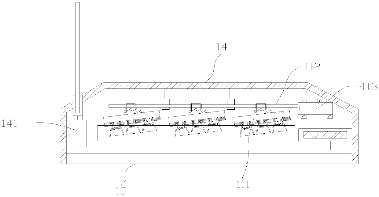
[0030] see Figure 1-Figure 7, the present invention provides a multifunctional integrated smart lamp: its structure includes a light box 1, a connecting rod 2, a banner 3, and a column 4, the light box 1 is fixedly connected to the connecting rod 2, and the banner 3 is provided with two All are fixedly connected with the column 4, and precautions can be hung on the banner 3, such as speed limit signs, signs of accident-prone places, or advertisements for investment promotion, etc. The connecting rod 2 is embedded and installed on the column 4, and the light box 1 is controlled by the Light emitting device 11, secondary light emitting device 12, substrate 13, housing 14, transparent cover 15, the main light emitting device 11 is installed on the c...


PUM


Abstract

The invention discloses an intelligent lamp integrating multiple functions. The intelligent lamp comprises a lamp box, a connecting rod, banners and stand columns, and the lamp box is fixedly connected with the connecting rod; the two banners are both fixedly connected with the stand columns. The connecting rod is embedded in the stand columns. The lamp box is composed of a main light-emitting device, an auxiliary light-emitting device, a base plate, a shell and a transparent cover shell. The main light-emitting device is installed on the central axis of the substrate. At least two sets of auxiliary light-emitting devices are arranged and located on one side of the main light-emitting device. The base plate is fixedly connected with the shell through a sealant, the transparent cover shellis connected with the shell through a buckle piece, and the shell is fixedly connected with the connecting rod. The irradiation direction of lamplight can be changed through direct control of a control room or by means of the programming technology in the evening peak period and the night period, and therefore the lamplight of the LED lamp can generate the corresponding using effect in different application scenes.

Description

technical field [0001] The invention is a multifunctional integrated smart lamp, which belongs to the field of street lamps. Background technique [0002] Street lights, as an important public facility that provides lighting for residents, have the characteristics of wide distribution and large quantities. Ensuring their good operation is also a key part of ensuring residents' safe travel at night. [0003] The prior art application number is 201821436036.4, an intelligent street lamp device based on the Internet of Things. Its structure includes a plurality of street lamps erected on both sides of the road and a geomagnetic sensor box installed in the road. The interior of the box is provided with a control circuit board and a street lamp control switch, the control circuit board is connected with the street lamp control switch, an infrared sensor is also provided on the light pole of the street lamp, a solar panel is provided on the top of the street lamp, and the solar T...

Claims


Application Information

Patent Timeline
Patent Type & Authority Applications(China)
IPC IPC(8): F21S8/08F21V1/14F21V5/00F21V19/00F21V23/06F21V33/00H05B45/10H05B45/30F21W131/103F21Y115/10
CPCF21S8/08F21V1/14F21V5/00F21V19/00F21V23/003F21V23/06F21V33/00H05B45/10H05B45/30F21W2131/103F21Y2115/10Y02B20/40
Inventor 陈连飞金园妹陈友莹
Owner 浙江瑞林光环境集团有限公司
Learn More