Battery thermal runaway monitoring, preventing and safety protecting system
A technology of safety protection and thermal runaway, applied in electrical transmission signal systems, secondary battery repair/maintenance, secondary batteries, etc., can solve the problems of no thermal runaway rescue measures, few monitoring and acquisition signals, and a single early warning mode, etc. The effect of low cost, safety protection, and safety improvement
- Summary
- Abstract
- Description
- Claims
- Application Information
AI Technical Summary
Problems solved by technology
Method used
Image

Examples
Embodiment
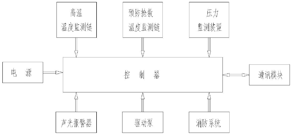
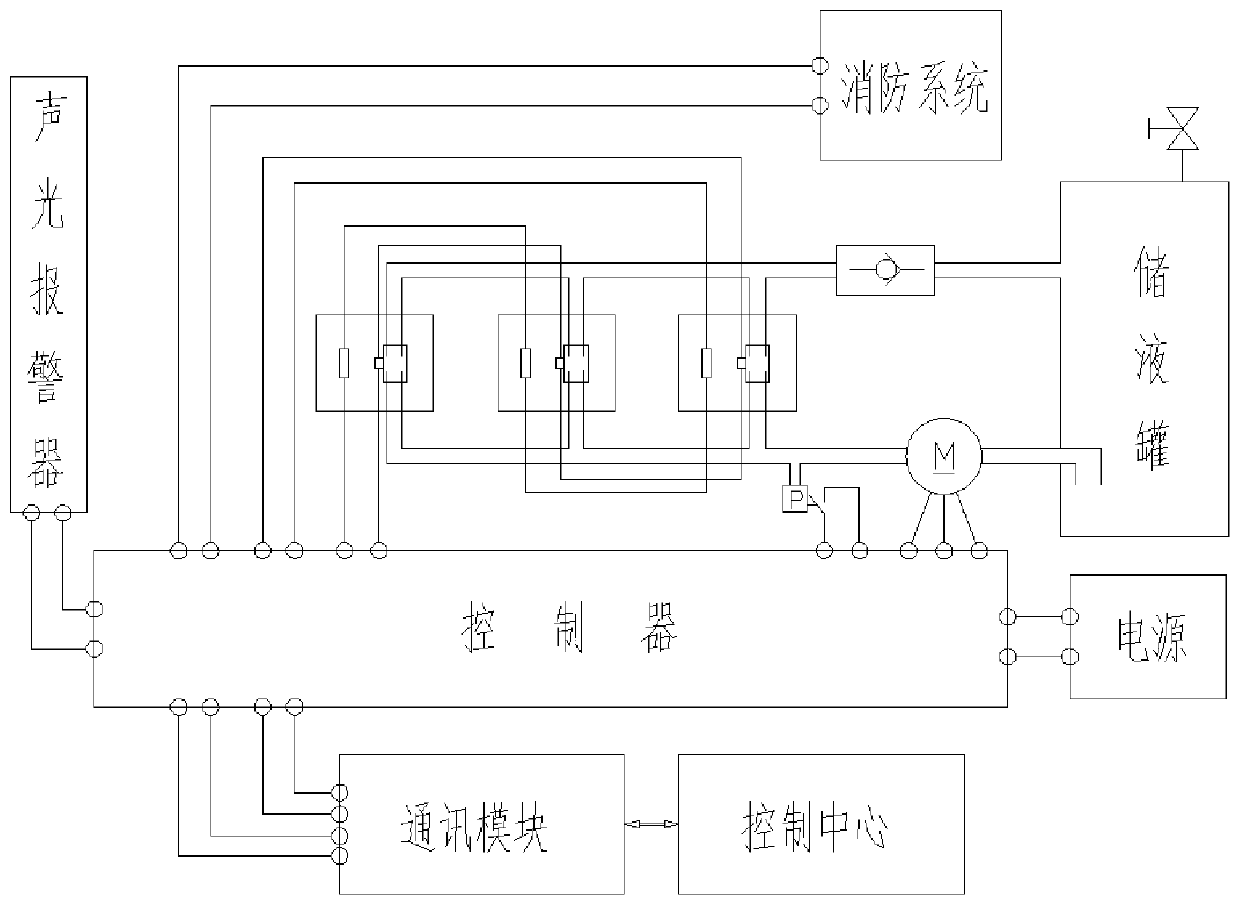
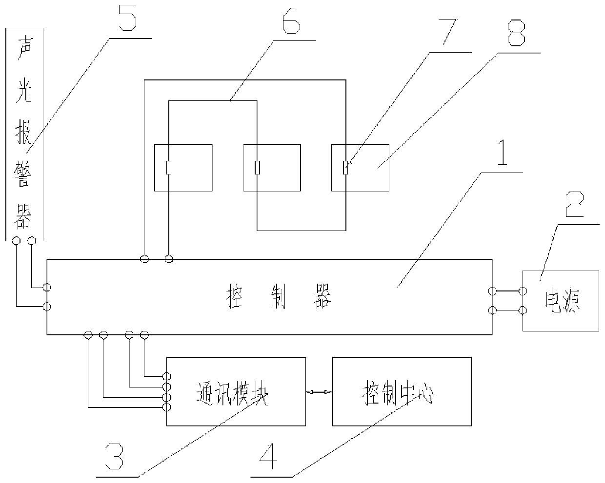
[0032] Embodiment: In this example, the monitoring, prevention and safety protection of 3 batteries are used as an example to illustrate, and more batteries can be used in practical applications.
[0033] Such as figure 1 , figure 2 As shown, a battery thermal runaway monitoring, prevention and safety protection system includes a high temperature alarm monitoring part, a thermal runaway prevention and rescue part, a thermal runaway safety protection part, a power supply 2, and a controller 1. The batteries 8 are respectively connected to high temperature On the high temperature monitoring chain 6 of the alarm monitoring part, on the temperature monitoring chain 9 and the connection circuit 17 of the prevention and rescue part of the thermal runaway prevention and rescue part, the pressure monitoring device 15 of the thermal runaway safety protection part is set on the connection circuit 17 of the thermal runaway prevention and rescue part , the sound and light alarm 5 of the...
PUM
 Abstract
Description
Claims
Application Information
 - Generate Ideas
- Intellectual Property
- Life Sciences
- Materials
- Tech Scout
- Unparalleled Data Quality
- Higher Quality Content
- 60% Fewer Hallucinations
Browse by: Latest US Patents, China's latest patents, Technical Efficacy Thesaurus, Application Domain, Technology Topic, Popular Technical Reports.
© 2025 PatSnap. All rights reserved.Legal|Privacy policy|Modern Slavery Act Transparency Statement|Sitemap|About US| Contact US: help@patsnap.com