Autonomous rainproof heat dissipation power distribution cabinet

An autonomous technology for power distribution cabinets, applied in substation/power distribution device housings, electrical components, substation/switch layout details, etc., can solve problems such as inability to close vents, potential safety hazards, rainwater easily entering power distribution cabinets, etc.

Active Publication Date: 2020-08-25
GUANGXI POWER GRID CORP
View PDF11 Cites 1 Cited by
  • Summary
  • Abstract
  • Description
  • Claims
  • Application Information

AI Technical Summary

Problems solved by technology

[0004] The purpose of the present invention is to solve the disadvantage that the existing power distribution cabinets in the prior art cannot close the vents in rainy days, so that rainwater can easily enter the power distribution cabinets and cause potential safety hazards. Rain-proof and heat-dissipating power distribution cabinet

Method used


Image

  • Autonomous rainproof heat dissipation power distribution cabinet
  • Autonomous rainproof heat dissipation power distribution cabinet
  • Autonomous rainproof heat dissipation power distribution cabinet

Examples


Embodiment 1

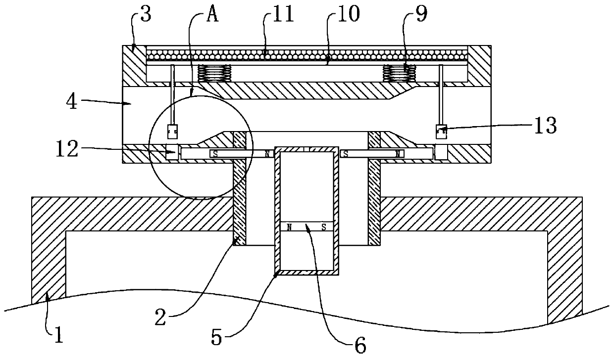
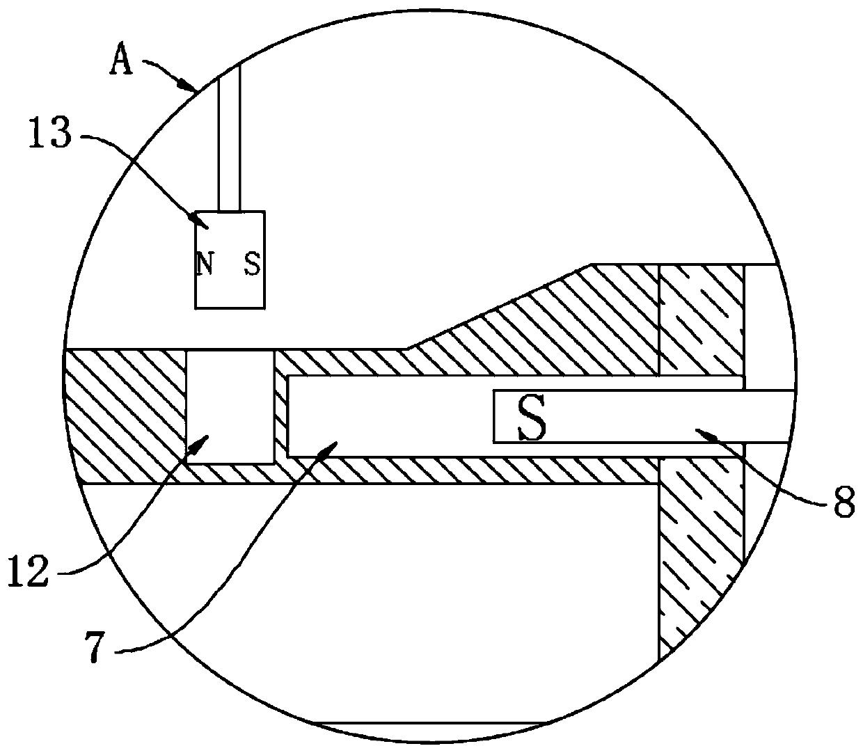
[0022] refer to Figure 1-2 , an autonomous rain-proof and heat-dissipating power distribution cabinet, including a box body 1, a conduit 2 inserted in the middle of the upper end of the box body 1, and the lower end of the conduit 2 communicates with the inside of the box body 1, and the upper end of the conduit 2 is fixedly connected with a fixing frame 3, fixed The frame 3 is horizontally provided with a flow groove 4, and the upper end of the conduit 2 communicates with the middle part of the flow groove 4, and the cross-sectional area at both ends of the flow groove 4 is larger than the cross-sectional area of ​​the middle part, that is, the flow groove 4 is in the form of a Venturi tube, and the upper end of the conduit 2 is connected to the middle of the flow groove 4. The communication part of the circulation groove 4 is located in the constriction section of the circulation groove 4, and the heat conduction cylinder 5 is arranged coaxially in the conduit 2, and the fir...

Embodiment 2

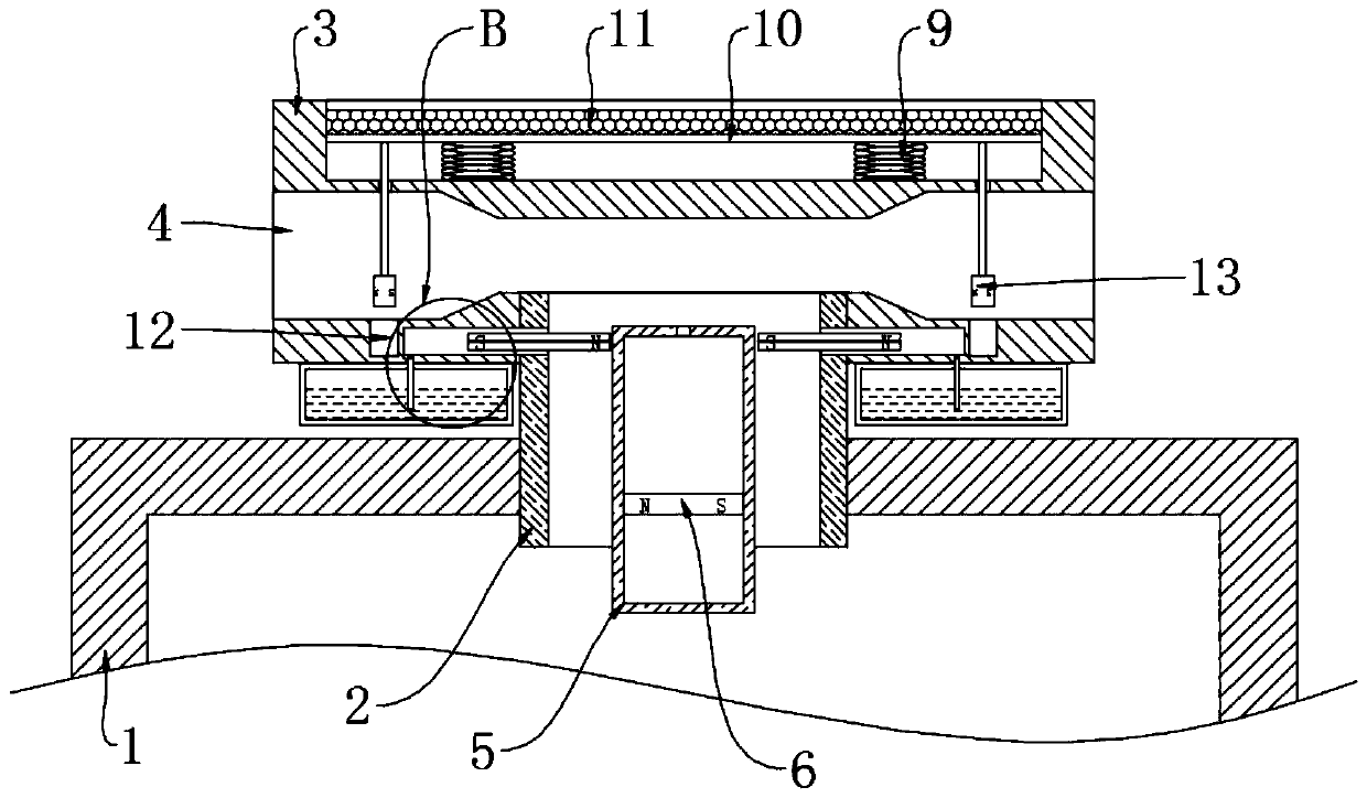
[0027] refer to Figure 3-4 The difference between this embodiment and Embodiment 1 is that each second permanent magnet block 8 is in sealing and sliding connection with the corresponding chute 7, and the end surface of the second permanent magnet block 8 away from the heat conduction cylinder 5 is connected with the chute 7 The sealed space formed is a temporary storage area, the temporary storage area and the installation box 14 are filled with insect repellent liquid, the lower end of the fixed frame 3 is symmetrically connected with the installation box 14 for storing the insect repellent liquid, and the installation box 14 corresponding to the position is connected to the temporary storage area. A one-way liquid inlet pipe 16 is connected between the zones. The one-way liquid inlet pipe 16 only allows the gas or liquid in the installation box 14 to enter the temporary storage area through the one-way liquid inlet pipe 16. Each second permanent magnet block 8 All are prov...


PUM


Abstract

The invention discloses an autonomous rainproof heat dissipation power distribution cabinet which comprises a box body; a guide pipe is inserted into the upper end of the box body; the upper end of the guide pipe is fixedly connected with a fixed frame; a circulating groove is horizontally formed in the fixed frame; the upper end of the guide pipe communicates with the middle of the circulating groove; a heat conduction cylinder is coaxially arranged in the guide pipe; a first permanent magnet block is connected into the heat conduction cylinder in a sealed and sliding mode, a sealed space formed by the lower end face of the first permanent magnet block and the heat conduction cylinder is filled with a driving agent, sliding grooves are symmetrically formed in the fixed frame, a second permanent magnet block is connected into each sliding groove in a sliding mode, and the magnetic poles of the opposite sides of two second permanent magnet blocks are opposite. When the autonomous rainproof heat dissipation power distribution cabinet is used, only when the temperature in the box body is too high, can the guide pipe be opened to dissipate heat in the box body, insect expelling liquidis sprayed to an inner hole, the pertinence is high, meanwhile, the guide pipe can be blocked in time during rainfall by arranging an expanding agent and a third permanent magnet block, and rainwateris prevented from entering the box body.

Description

technical field [0001] The invention relates to the technical field of power equipment, in particular to an autonomous rainproof and heat dissipation power distribution cabinet. Background technique [0002] According to the needs, there are many power distribution cabinets installed outdoors in reality. The power distribution cabinets installed outdoors are usually closed to prevent theft, mosquitoes and rain. However, there are often many power devices installed in the power distribution cabinets. More heat will be generated during operation, and the gas fluidity inside the power distribution cabinet in a closed state will cause the internal heat of the power distribution cabinet to be unable to be discharged in time, which will affect the operation of the power devices inside the power distribution cabinet, and even reduce the power of these power devices. service life. [0003] To this end, we propose an autonomous rain-proof and heat-dissipating power distribution cabi...

Claims


Application Information

Patent Timeline
Patent Type & Authority Applications(China)
IPC IPC(8): H02B1/30H02B1/46H02B1/56H02B1/28A01M29/12
CPCA01M29/12H02B1/28H02B1/30H02B1/46H02B1/565
Inventor 任宗愈
Owner GUANGXI POWER GRID CORP
Why Eureka
Try Eureka