A full cold-shrinkable cable terminal
A cable terminal and terminal technology, applied in the direction of cable terminals, etc., can solve the problems of complex process, time-consuming and laborious, unsatisfactory installation effect, etc., and achieve the effect of improving positioning protection and simple and convenient operation
- Summary
- Abstract
- Description
- Claims
- Application Information
AI Technical Summary
Problems solved by technology
Method used
Image
Examples
Embodiment 1
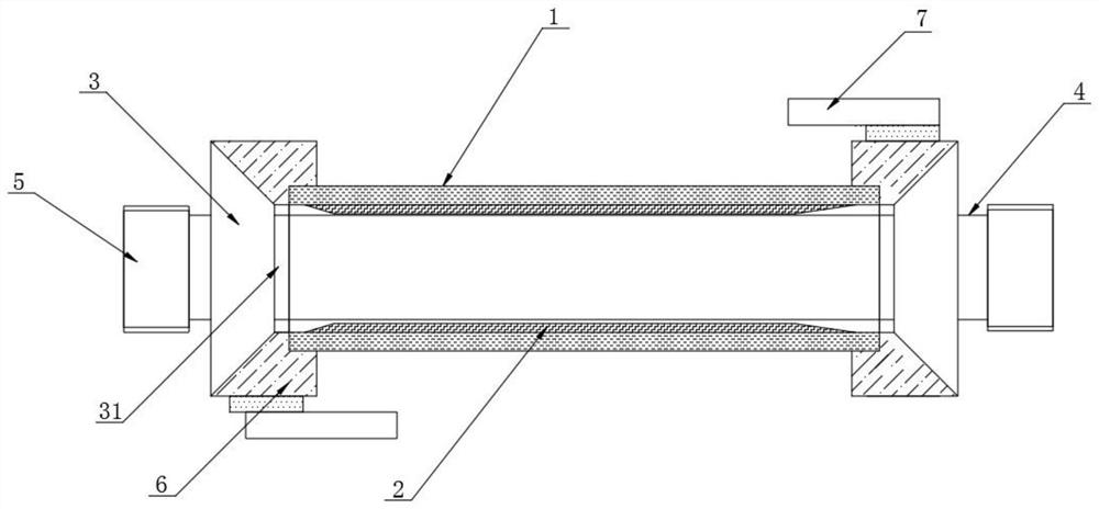
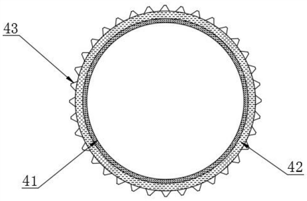
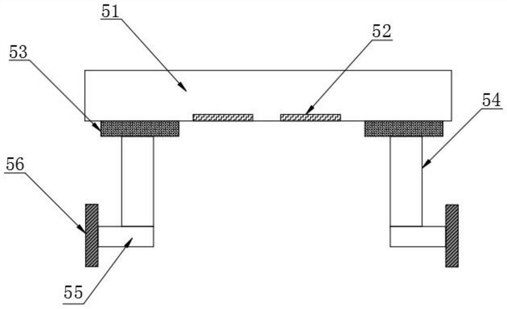
[0022] The present invention provides such as Figure 1-4 A fully cold-shrinkable cable terminal shown includes a terminal body 1, a stress cone 2 is provided inside the terminal body 1, shed skirts 3 are provided on the left and right sides of the terminal body 1, and the inside of the stress cone 2 A positioning frame 4 is provided, and the positioning frame 4 includes a positioning collar 41, a sealing ring 42 and a bump 43. The left and right sides of the positioning frame 4 are provided with a positioning device 5, and the positioning device 5 includes a positioning seat 51, The connection hole 52, the inserting plate 53, the first telescopic rod 54, the support plate 55 and the close plate 56, the sealing block 6 is provided on the outside of the umbrella skirt 3, and the connecting device 7 is provided on the outside of the sealing block 6.
[0023] Further, the terminal main body 1, the stress cone 2 and the shed 3 are all made of silicone rubber material, the terminal...
Embodiment 2
[0027] Further, the positioning seat 51 is arranged on the outer side of the umbrella skirt 3 in the left-right direction, and the positioning seat 51 is evenly provided with connecting holes 52 on the inner wall of the umbrella skirt 3 in the left-right direction, and the positioning seat 51 is arranged on the left-right direction. On the side close to the umbrella skirt 3, there is an inserting plate 53, the side of the inserting plate 53 close to the positioning seat 51 is provided with an inserting rod matching the connecting hole 52, and the other side of the inserting plate 53 is provided with The first telescopic rod 54, the side of the first telescopic rod 54 away from the insertion plate 53 is provided with a support plate 55 extending perpendicular to the first telescopic rod 54, and the support plate 55 is screwed to the first telescopic rod 54, An abutment plate 56 is fixed on the outer side of the support plate 55 in its extending direction.
[0028] Further, the ...
PUM
 Abstract
Description
Claims
Application Information
 - R&D
- Intellectual Property
- Life Sciences
- Materials
- Tech Scout
- Unparalleled Data Quality
- Higher Quality Content
- 60% Fewer Hallucinations
Browse by: Latest US Patents, China's latest patents, Technical Efficacy Thesaurus, Application Domain, Technology Topic, Popular Technical Reports.
© 2025 PatSnap. All rights reserved.Legal|Privacy policy|Modern Slavery Act Transparency Statement|Sitemap|About US| Contact US: help@patsnap.com


