Dc-dc converter

A converter and AC conversion technology, applied in the direction of output power conversion devices, high-efficiency power electronic conversion, instruments, etc., can solve the problems of different switching frequencies, output voltage and output current pulsation, etc., and achieve the goal of preventing pulsation and output current balance Effect

Pending Publication Date: 2020-08-25
FUJI ELECTRIC CO LTD
View PDF12 Cites 0 Cited by
  • Summary
  • Abstract
  • Description
  • Claims
  • Application Information

AI Technical Summary

Problems solved by technology

[0019] According to this prior art, since the output voltage V of the converter unit 100, 200 o1 , V o2 Consistent, so the average power output from each unit is relatively balanced, but because the switching frequency of each unit is different, there is a problem that the output voltage and output current pulsate at a frequency lower than the switching frequency

Method used


Image

  • Dc-dc converter
  • Dc-dc converter
  • Dc-dc converter

Examples


Embodiment Construction

[0059] Hereinafter, embodiments of the present invention will be described with reference to the drawings.

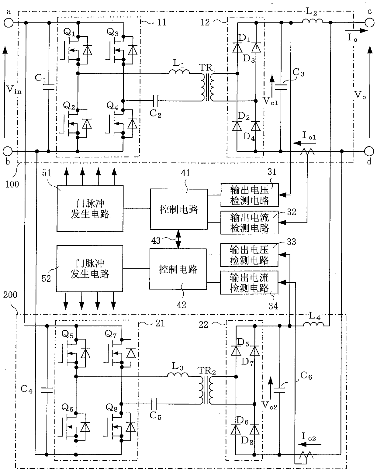
[0060] figure 1 It is a block diagram of the DC-DC converter device of this embodiment. The converter units 100, 200 are connected in parallel between the DC input terminals a, b and the DC output terminals c, d, and the configurations of each unit 100, 200 are respectively the same as Figure 5 , Figure 6 ,and Figure 9 the same as the prior art.

[0061] The control device of the converter unit 100 has the output voltage detection circuit 31, the output current detection circuit 32, the control circuit 41, and the gate pulse generation circuit 51 of the unit 100, and the control device of the converter unit 200 has the output voltage detection circuit of the unit 200. Circuit 33 , output current detection circuit 34 , control circuit 42 , and gate pulse generation circuit 52 .

[0062] Here, in this embodiment, the control circuit 41 of the converter unit 100 an...


PUM


Abstract

Provided is a DC-DC converter which, when multiple converter units are operated in parallel, eliminates fluctuations in the output voltage, eliminates imbalances among the output currents of the converter units, and eliminates pulsations in the output voltage and output current. Specifically provided is a DC-DC converter in which current resonant converter units 100, 200 are connected in parallel,and a control device comprising a control circuit 41, 42, a gate pulse generation circuit 51, 52, etc., is provided for each converter unit 100, 200. As a common switching frequency, the control circuits 41, 42 share the lowest of the switching frequencies corresponding to output voltages that are the same in terms of a characteristic indicating the relationship between the switching frequency and the output voltage of the converter units 100, 200, and the converter units 100, 200 are operated using a drive pulse which has the common switching frequency.

Description

technical field [0001] The present invention relates to a DC-DC converter device constituted by parallel connection of a plurality of converter units performing DC-DC conversion. Background technique [0002] Figure 5 A first prior art of such a DC-DC converter device is shown. [0003] Figure 5 Among them, 100 and 200 are current resonance type converter units for DC-DC conversion. These converter units 100 and 200 have the same configuration, and input terminals a, b and output terminals c, d are connected in parallel with each other. [0004] 11 and 21 are the DC input voltage (capacitor C 1 、C 4 The voltage across the) V in The DC-AC conversion part converted into AC voltage is composed of semiconductor switching elements Q 1 ~Q 4 , Q 5 ~Q 8 The full-bridge circuit constitutes. [0005] The AC output terminal of the DC-AC conversion unit 11 passes through the resonance reactor L 1 , Resonant capacitor C 2 , and insulation transformer TR 1 with diode D 1 ~D...

Claims


Application Information

Patent Timeline
IPC IPC(8): H02M3/155H02J1/10H02M3/28
CPCH02M3/3376H02M3/285H02M3/33515Y02B70/10H02M1/0003H02M1/0058H02M1/0043H02M3/33573H02M3/01H02M3/33571H02M3/158H02M3/33507H02M7/5387
Inventor 鹢头政和
Owner FUJI ELECTRIC CO LTD
Why Eureka
Try Eureka