Adjustable treatment chair

A therapeutic chair and adjustable technology, applied in the field of medical devices, can solve the problems of unable patients to treat, relieve and exercise.

Active Publication Date: 2020-08-28
HARBIN QUANKE MEDICAL TECH DEV
View PDF12 Cites 4 Cited by
  • Summary
  • Abstract
  • Description
  • Claims
  • Application Information

AI Technical Summary

Problems solved by technology

However, the device cannot treat, relieve and exercise the patient's vision

Method used


Image

  • Adjustable treatment chair
  • Adjustable treatment chair
  • Adjustable treatment chair

Examples


specific Embodiment approach 1

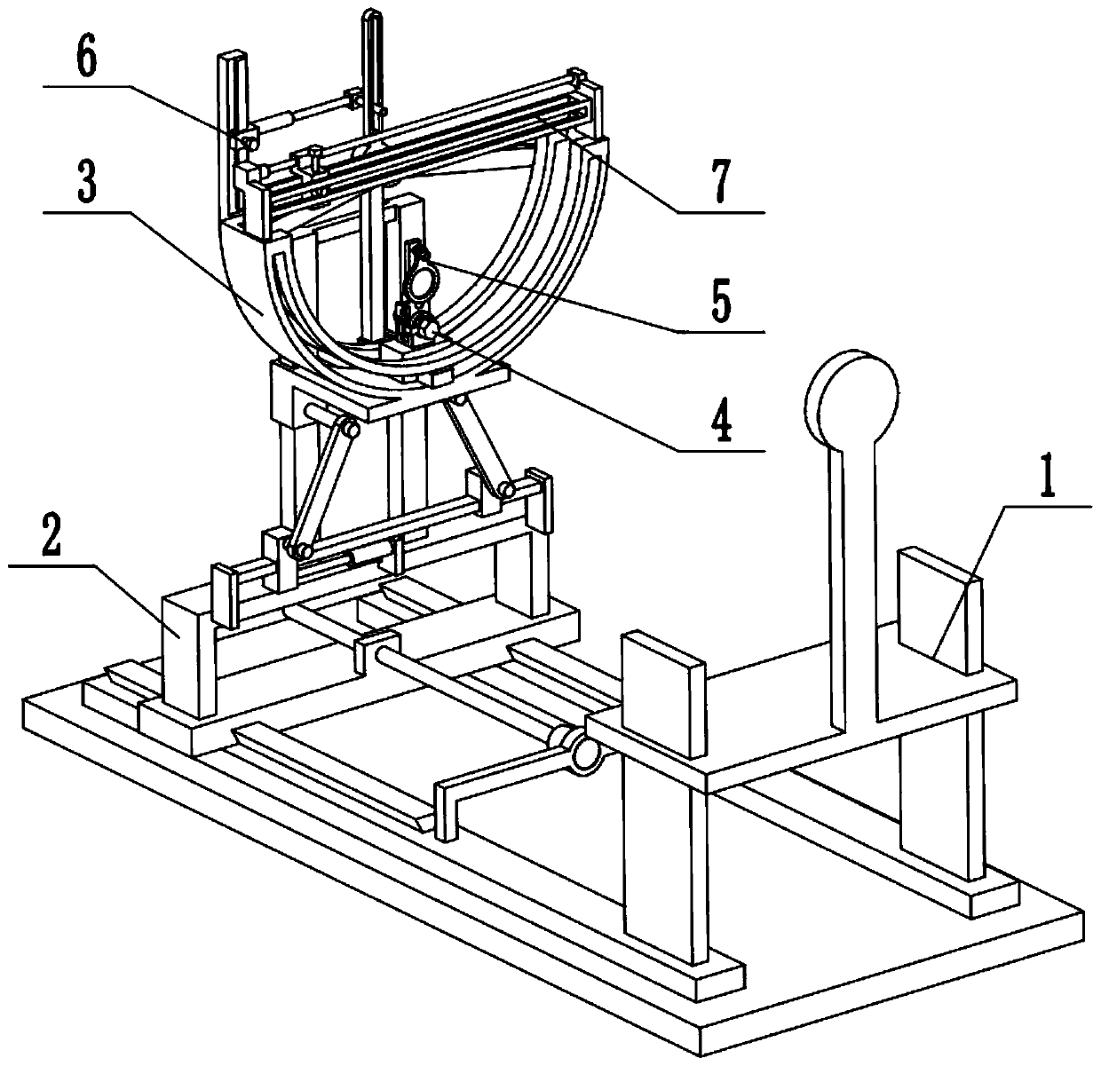
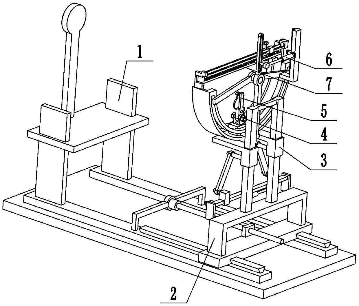
[0033] Combine below Figure 1-8Describe this embodiment, an adjustable treatment chair, including a treatment chair body 1, a movable adjustment seat 2, a turret 3, a reciprocating slide 4, a vision treatment restoration part 5, a reciprocating adjustment part 6 and a level adjustment part 7. The movable adjustment seat 2 is connected to the treatment chair body 1, the turret 3 is arranged on the movable adjustment seat 2, the reciprocating slider 4 is movably connected in the turret 3, and the vision treatment restoration part 5 is detachably connected to the reciprocating slider 4 Above, the reciprocating adjustment part 6 is arranged on the turret 3, the reciprocating adjustment part 6 is connected with the reciprocating slide 4, and the horizontal adjustment part 7 is arranged on the upper end of the turret 3; When in use, the patient sits on the treatment chair body 1, and the distance between the movable adjustment seat 2 and the patient can be adjusted, which is suitab...

specific Embodiment approach 2

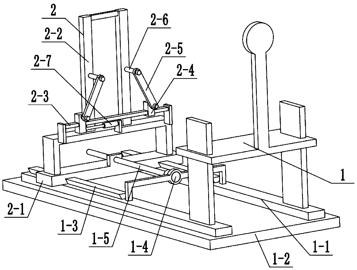
[0035] Combine below Figure 1-8 To illustrate this embodiment, the treatment chair body 1 is provided with a bottom plate 1-1, a base 1-2, a trapezoidal rod 1-3, a first motor 1-4 and a screw 1-5; the treatment chair body 1 is fixedly connected to The front ends of the two base plates 1-1, the two base plates 1-1 are fixedly connected to the base 1-2, the rear ends of the two base plates 1-1 are respectively fixedly connected to a trapezoidal rod 1-3, and the first motor 1-4 passes through The motor frame is fixedly connected on the two bottom plates 1-1, the output shaft of the first motor 1-4 is connected to the screw rod 1-5 through a coupling, and the movable adjusting seat 2 is connected with the screw rod 1-5. When in use, the patient sits on the treatment chair body 1, and the first motor 1-4 drives the movable adjustment seat 2 to move back and forth through the screw rod 1-5 after the first motor 1-4 is started, changing the distance between the movable adjustment se...

specific Embodiment approach 3

[0037] Combine below Figure 1-8 To illustrate this embodiment, the movable adjustment seat 2 includes a sliding seat 2-1, a portal frame 2-2, a portal frame 2-3, a slider 2-4, a hinged rod 2-5, and a short shaft 2- 6 and the electric push rod 2-7; the sliding seat 2-1 is slidably connected to the two trapezoidal rods 1-3, the sliding seat 2-1 and the screw rod 1-5 are connected through screw threads, and the portal frame 2-2 and the door The sliding frame 2-3 is all fixedly connected on the sliding seat 2-1, and the two sliding blocks 2-4 are symmetrically slidingly fitted and connected on the door type sliding frame 2-3, and the two sliding blocks 2-4 are respectively rotated and connected to a Hinged rod 2-5, two articulated rods 2-5 are connected with a short axis 2-6 respectively, the two short shafts 2-6 are all arranged on the turret 3, and the electric push rod 2-7 is fixedly connected to the trapezoidal rod 1-3, the telescopic end of the electric push rod 2-7 is fixe...


PUM


Abstract

The invention discloses an adjustable treatment chair and relates to the technical field of medical instruments. The adjustable treatment chair comprises a treatment chair body, a movable adjusting seat, a rotating frame, a reciprocating sliding part, an eyesight treatment recovery part, a reciprocating adjusting part and a horizontal adjusting part. The adjustable treatment chair has the beneficial effects as follows: the adjustable treatment chair has treatment, relieving and exercise functions on the eyesight of a patient by exercising the contractility of crystalline lenses, and has multiple modes. The movable adjusting seat is connected to the treatment chair body in a matched manner, the rotating frame is arranged on the movable adjusting seat, the reciprocating sliding part is movably connected in the rotating frame, the eyesight treatment recovery part is detachably connected to the reciprocating sliding part, the reciprocating adjusting part is arranged on the rotating frame,the reciprocating adjusting part and the reciprocating sliding part are connected in a matched manner, and the horizontal adjusting part is arranged at the upper end of rotating frame; and the treatment chair body and the movable adjusting seat are arranged oppositely.

Description

technical field [0001] The invention relates to the technical field of medical equipment, in particular to an adjustable treatment chair. Background technique [0002] Patent No. CN201720866030.X is an ophthalmic treatment chair. The utility model discloses an ophthalmic treatment chair, which relates to the technical field of medical devices. The ophthalmic treatment chair includes a chair surface, chair legs, armrests and a backrest. By setting a headrest on the backrest support frame, the headrest includes two headrest cushions supported by the head trays, which can support and support the patient's back of the head on both sides. The fixed function makes the patient's head not easy to deflect, and better cooperates with eye treatment; there are cheek pads on both sides of the head rest. When the patient needs to turn sideways for eye treatment, the cheek pads can support the patient's face And fixation, improve the patient's comfort, improve the patient's cooperation, a...

Claims


Application Information

Patent Timeline
IPC IPC(8): A61H5/00
CPCA61H5/00A61H2205/024
Inventor 王祥林王晓艳孙卫建祝序文杨烁杨鸿亮
Owner HARBIN QUANKE MEDICAL TECH DEV
Why Eureka
Try Eureka