Foot pad picking and placement mechanism

A foot pad and mechanical arm technology, applied in the field of automation equipment, can solve the problems of easily damaged foot pads, small foot pads, difficult to hold, etc. Effect

Pending Publication Date: 2020-08-28
MITAC PRECISION TECH(KUNSHAN) CORP
View PDF5 Cites 1 Cited by
  • Summary
  • Abstract
  • Description
  • Claims
  • Application Information

AI Technical Summary

Problems solved by technology

[0003] Existing pick-and-place mechanisms are generally divided into two types. One is to use grippers to hold and place, but due to the small size of the pads, it is not easy to clamp, and the clamping force is too large to easily damage the pads; the other is Pick-and-place by vacuum suction, that is, the foot pad is absorbed by the suction head, and then moved to the assembly position by the manipulator
However, when the vacuum adsorption force is small and the bonding force between the foot pad and the foot pad auxiliary material is large, it is difficult to remove the foot pad from the foot pad auxiliary material, resulting in the leakage of the foot pad.

Method used


Image

  • Foot pad picking and placement mechanism
  • Foot pad picking and placement mechanism
  • Foot pad picking and placement mechanism

Examples


Embodiment Construction

[0024] The technical solutions of the present invention will be further described below in conjunction with the accompanying drawings and through specific implementation methods.

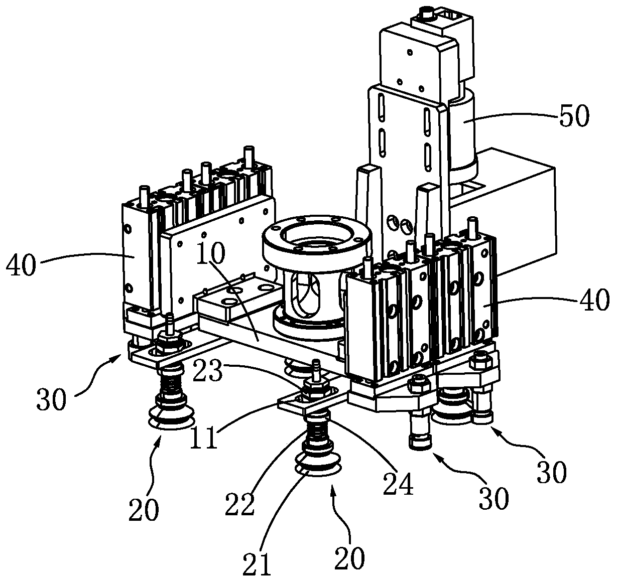
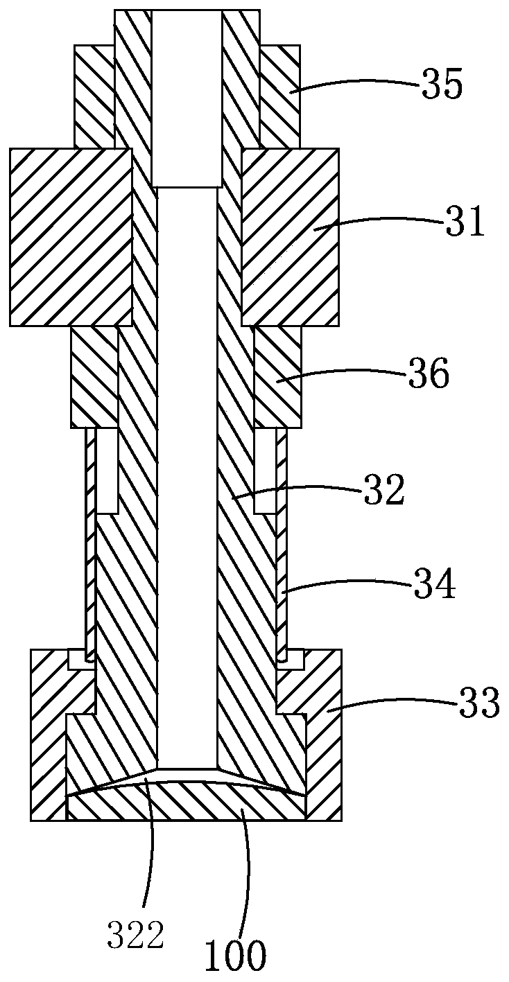
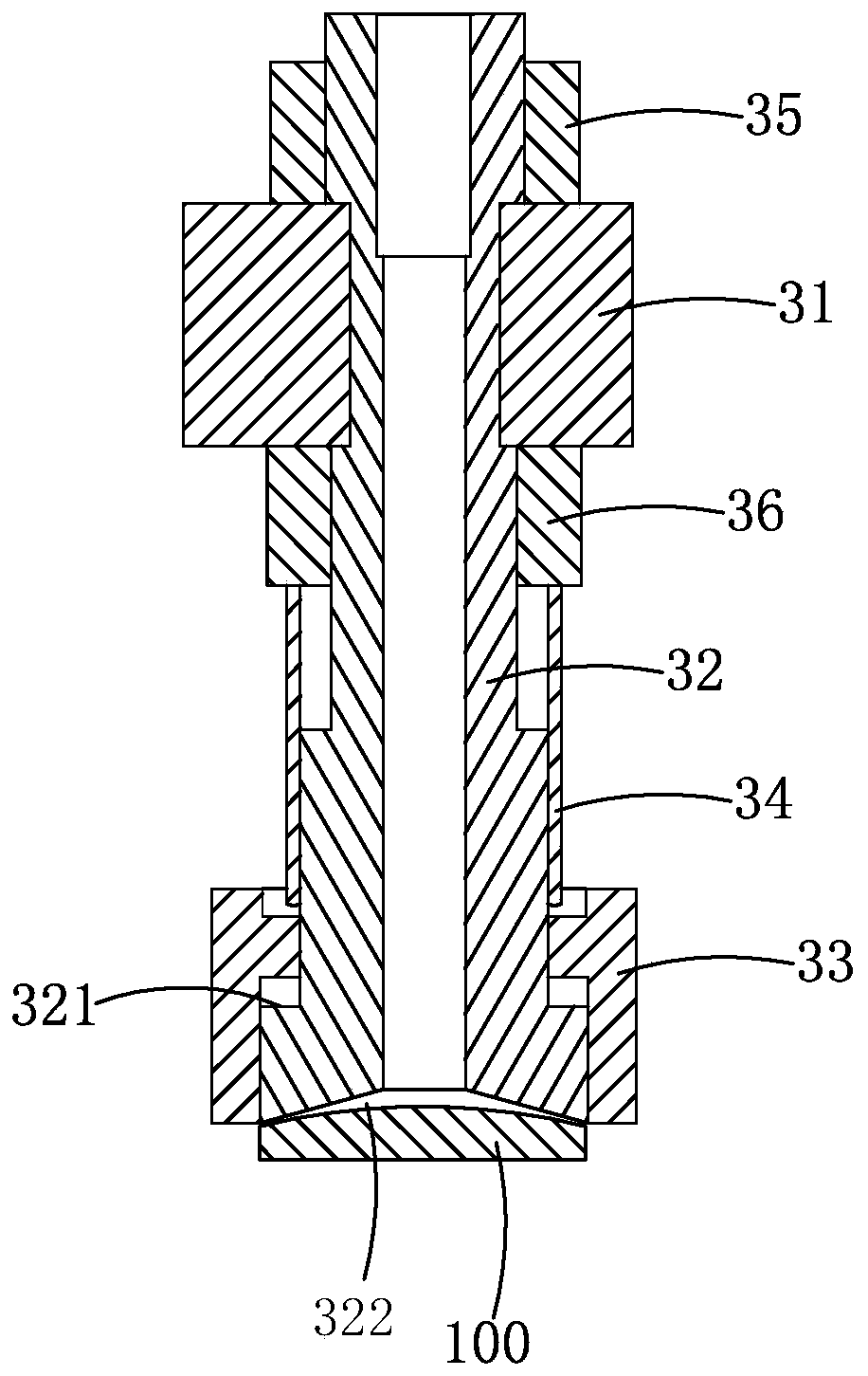
[0025] Such as Figure 1-3 As shown, a foot pad pick-and-place mechanism includes a bracket 10, at least two first elastic adsorption components 20, at least one second elastic adsorption component 30, a driving device 40, a visual positioning device 50 and a mechanical arm (not shown in the figure) . Wherein, each first elastic adsorption assembly 20 is connected on the support 10, and is used for absorbing foot pad accessories (ie release film); the second elastic adsorption assembly 20 is used for absorbing foot pads 100 positioned on the foot pad auxiliary materials; It is used to drive the second elastic adsorption component 20 to move up and down relative to the bracket 10; the visual positioning device 50 is connected to the bracket 10 for visual positioning when picking and placing the foot...


PUM


Abstract

The invention relates to the field of automatic equipment, and particularly discloses a foot pad picking and placement mechanism. The foot pad picking and placement mechanism comprises a support, a mechanical arm driving the support to move in a three-dimensional space, at least one second elastic suction assembly arranged on the support, and a driving device driving the second elastic suction assembly to move up and down relative to the support, wherein the second elastic suction assembly comprises a connecting plate, a second vacuum suction head connected with the connecting plate, a sleeveand an elastic piece; the outer periphery of the second vacuum suction head is coaxially sleeved by the sleeve; the elastic piece is arranged between the sleeve and the connecting plate, and can extend and retract along the central axis of the second vacuum suction head; and in an initial state, one end of the sleeve extends out of a suction end of the second vacuum suction head. The foot pad picking and placement mechanism disclosed by the invention has the advantages that a foot pad can be accurately picked and placed, so that the problem that the foot pad is omitted during adhesion is effectively solved, and the use is more convenient.

Description

【Technical field】 [0001] The invention relates to the field of automation equipment, in particular to a foot pad pick-and-place mechanism. 【Background technique】 [0002] Existing electronic products such as notebooks, mice, keyboards, etc., usually attach foot pads at the bottom in order to reduce wear and shock absorption. In assembly, a pick-and-place mechanism is usually used to remove multiple foot pads on the foot pad accessories in sequence, and move to the assembly position to stick on the product. [0003] Existing pick-and-place mechanisms are generally divided into two types. One is to use grippers to hold and place, but due to the small size of the pads, it is not easy to clamp, and the clamping force is too large to easily damage the pads; the other is Pick-and-place by vacuum suction, that is, the foot pad is absorbed by the suction head, and then moved to the assembly position by the manipulator. However, when the vacuum adsorption force is small and the coh...

Claims


Application Information

Patent Timeline
Patent Type & Authority Applications(China)
IPC IPC(8): B25J9/00B25J9/14B25J15/06F16B11/00
CPCB25J9/00B25J9/144B25J15/0616F16B11/006
Inventor 马一凡
Owner MITAC PRECISION TECH(KUNSHAN) CORP
Why Eureka
Try Eureka