Brake release method for robot, robot and device with storage function

A technology of robots and robot joints, which is applied in the field of robots, can solve problems such as time waste, efficiency reduction, brake heating, etc., and achieve the effects of reducing the number of pulses, improving service life, and saving time

Active Publication Date: 2021-11-02
PEITIAN ROBOTICS CO LTD
View PDF6 Cites 0 Cited by
  • Summary
  • Abstract
  • Description
  • Claims
  • Application Information

AI Technical Summary

Problems solved by technology

[0004] Since the rated operating voltage of the brake is 5V, multiple pulses sent continuously will cause the brake to heat up and the coil to expand, thereby reducing the service life of the brake; in addition, in some cases, the first few 48V pulses can make the gear The rod is retracted, and the subsequent multiple pulses sent are useless, which leads to wasted time and reduced efficiency

Method used


Image

  • Brake release method for robot, robot and device with storage function
  • Brake release method for robot, robot and device with storage function
  • Brake release method for robot, robot and device with storage function

Examples


Embodiment Construction

[0018] The following will clearly and completely describe the technical solutions in the embodiments of the present application with reference to the drawings in the embodiments of the present application. Obviously, the described embodiments are only some of the embodiments of the present application, not all of them. Based on the embodiments in this application, all other embodiments obtained by persons of ordinary skill in the art without making creative efforts belong to the scope of protection of this application.

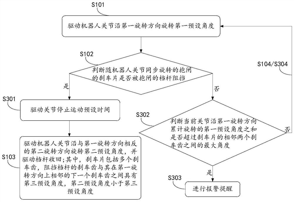
[0019] see figure 1 , figure 1 It is a schematic flow chart of an implementation mode of the robot brake release method of the present application, and the brake release method includes:

[0020] S101: Drive the joints of the robot to rotate along a first rotation direction by a first preset angle.

[0021] Specifically, in this embodiment, the execution subject of the above step S101 may be a servo driver, a servo driver is a controller used to control a se...


PUM


Abstract

The present application discloses a robot brake release method, a robot and a device with a storage function. The brake release method includes: driving the robot joints to rotate along a first rotation direction at a first preset angle; Whether the rotating brake pad of the holding brake is blocked by the gear lever of the holding brake; if so, drive the robot joint to rotate a second preset angle in a second rotation direction opposite to the first rotation direction, and Drive the shift lever back, wherein the brake pad includes a plurality of brake teeth, and there is a gap between the brake tooth that blocks the shift lever and the next adjacent brake tooth in the first rotation direction. A third preset angle, the second preset angle being smaller than the third preset angle; otherwise, returning to the step of driving the robot joint to rotate along the first rotation direction by the first preset angle. Through the above method, the gear lever can be retracted relatively easily.

Description

technical field [0001] The present application relates to the technical field of robots, in particular to a method for releasing a brake of a robot, a robot and a device with a storage function. Background technique [0002] When the robot is in the disabled state, due to the action of gravity, the brake pads and gear levers in the brakes corresponding to each joint will press against each other, generating a large friction force to prevent the joints from moving in a large range. When the robot is in the enabled state, the gear lever of the brake needs to be retracted to release the brake. Only after the brake is released, the joint can move in a large range. However, due to friction, the lever may become stuck and cannot be withdrawn. [0003] At present, when the robot is enabled, the way to retract the gear lever is as follows: the servo driver continuously sends multiple 48V pulses to the coil located on the periphery of the gear lever in the brake, and each pulse will...

Claims


Application Information

Patent Timeline
Patent Type & Authority Patents(China)
IPC IPC(8): B25J9/00B25J9/10B25J9/16
CPCB25J9/00B25J9/0009B25J9/10B25J9/16
Inventor 秦帆
Owner PEITIAN ROBOTICS CO LTD
Why Eureka
Try Eureka