
Heating device and temperature control device

Inactive Publication Date: 2013-02-21
TSAI MING WEI +1
View PDF0 Cites 18 Cited by
  • Summary
  • Abstract
  • Description
  • Claims
  • Application Information

AI Technical Summary

Benefits of technology

The present invention provides a heating device and temperature control device that can conduct heat uniformly and dissipate heat efficiently, and are safe in use. The heating element is controlled by a controller chip that applies a variation of voltages to it, resulting in more accurate temperature control. The device can be applied to various fields such as far-infrared heating blankets, warming utensils, electric blankets, heating massage pillows, heating straps for motorcycle handles, heater for vehicle rearview mirror, far-infrared heating helmets, outdoor heating seat cushions, food warming bags, heaters for vehicle tires, heating jackets, heating pads, etc. The technical effects of the invention include effective heating and temperature maintaining, overcoming the non-uniform heating and slow heat dissipation problems of the prior art.

Problems solved by technology

However, when a large area is heated by using the heating filaments or heating plates, the heat distribution in such a large area will be non-uniform.
Moreover, when the heating device with the metallic plate for conducting heat is used, heating and heat dissipating are slow.
Conventionally, in the first case, the heating devices can have heating function but without temperature control, but for these heating devices, heating is slow, the heating temperature will be continuously raised, and electricity consumption is high.
Conventionally, in the second case, the heating devices can also have heating with temperature control function, but for these heating devices, the temperature control is usually not accurate.
However, if the heating devices have accurate temperature control function, they are very expensive.
Furthermore, the current heating products will remain in the “on” state after they are switched on, which are power-consuming and not safe in use.
Consequently, the heating temperature becomes not stable for the heating device, and thereby the manual adjustment is required, which will cause inconvenience and inaccuracy.

Method used


Image

  • Heating device and temperature control device
  • Heating device and temperature control device
  • Heating device and temperature control device

Examples


Embodiment Construction

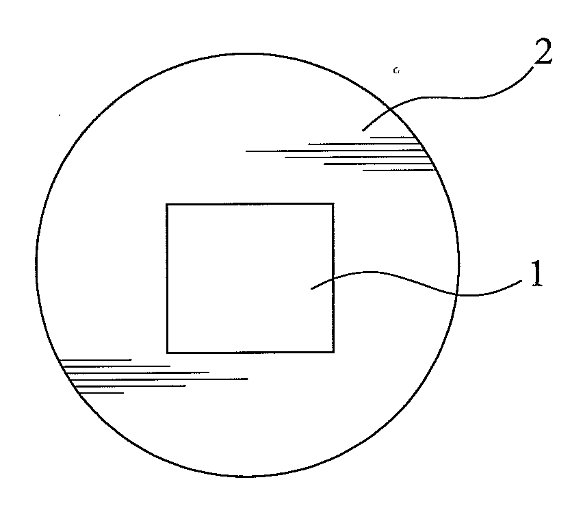
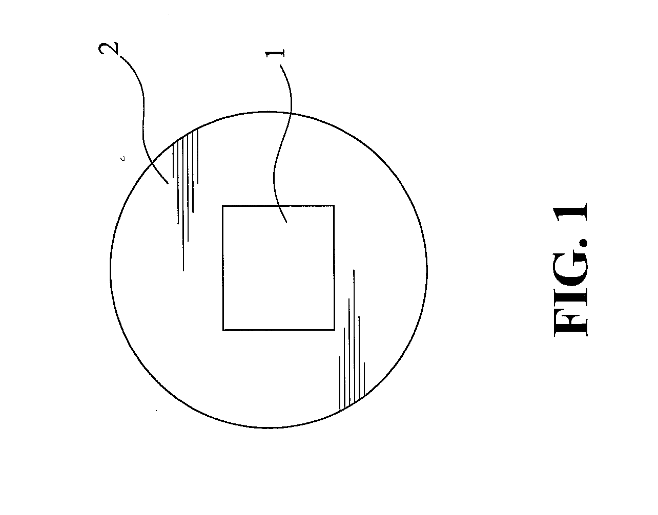
[0020]FIG. 1 is a schematic view showing a heating device according to one embodiment of the present invention. The heating device comprises a heating element 1, and a heat conducting film 2 disposed on the surface of the heating element 1. The heat conducting film 2 has a surface area that is larger than the contact area between the heat conducting film 2 and the heating element 1. The heating element is selected from at least one of the group consisting of PTC heating elements, ceramic electrothermal boards, silicon carbide tube heating elements, metal heating elements, carbon crystal heating elements, graphite heating elements, quartz heating elements, molybdenum disilicide heating elements, electrothermal filaments, thick film stencil, carbon fiber quartz heating elements, nano electrothermal film heating plates, and superconductor heating elements. The heat conducting film 2 is a metallic film, such as aluminum foil film having good heat conducting properties. The metallic film...


PUM


Abstract

A heating device and a temperature control device are provided. The heating device includes a heating element, and a heat conducting film disposed on the surface of the heating element, wherein the heat conducting film has a surface area that is larger than the contact area between the heat conducting film and the heating element. The heat conducting film is used for uniformly conducting heat generated by the heating element. Therefore, the existing non-uniform heating and slow heat dissipation problems for the heating element having a large surface area can be solved. Furthermore, because the metallic heat conducting film has good heat conduction, the heat can be quickly spread over a larger area to prevent localized overheating and damage to the heating element itself or the electrical product.

Description

BACKGROUND OF THE INVENTION[0001]1. Field of the Invention[0002]The present invention relates to a heating equipment, and more particularly to a heating device and a temperature control device.[0003]2. The Prior Arts[0004]Nowadays, the heating elements usually include heating filaments, heating plates, heating disks, and heating tubes. However, when a large area is heated by using the heating filaments or heating plates, the heat distribution in such a large area will be non-uniform. Moreover, when the heating device with the metallic plate for conducting heat is used, heating and heat dissipating are slow.[0005]Conventionally, in the first case, the heating devices can have heating function but without temperature control, but for these heating devices, heating is slow, the heating temperature will be continuously raised, and electricity consumption is high. Conventionally, in the second case, the heating devices can also have heating with temperature control function, but for thes...

Claims


Application Information

Patent Timeline
IPC IPC(8): H05B3/02H05B1/02H05B3/20
CPCH05B3/20H05B2203/013H05B3/84H05B3/34
Inventor TSAI, MING-WEIHUANG, MIN-LANG
Owner TSAI MING WEI
Learn More