
Heat diaphragm forming system

A thermal diaphragm forming and diaphragm technology, which is applied in the field of thermal diaphragm forming systems, can solve problems such as burns, affecting product consistency, and low processing efficiency of thermal diaphragm forming parts, so as to improve efficiency and reduce risks.

Active Publication Date: 2020-08-28
NEWTRY COMPOSITE
View PDF6 Cites 0 Cited by
  • Summary
  • Abstract
  • Description
  • Claims
  • Application Information

AI Technical Summary

Problems solved by technology

[0003] In the prior art, the processing efficiency of thermal diaphragm forming parts is not high. In each step of the thermal diaphragm forming process, too much manual participation is required, such as diaphragm laying and moving, such as vacuuming and heating the mold before the mobile
[0004] However, on the one hand, the above-mentioned manual operation process will affect the consistency of the product, making it difficult to control the quality of the product. On the other hand, there are also dangerous factors in the manual participation. Mishandling can cause burns

Method used


Image

  • Heat diaphragm forming system
  • Heat diaphragm forming system
  • Heat diaphragm forming system

Examples


Embodiment Construction

[0038] The following will clearly and completely describe the technical solutions in the embodiments of the present invention with reference to the accompanying drawings in the embodiments of the present invention. Obviously, the described embodiments are only some, not all, embodiments of the present invention.

[0039] It should be noted that when an element is referred to as being "fixed" to another element, it can be directly on the other element or there may be an intervening element. When an element is said to be "connected" to another element, it can be directly connected to the other element or intervening elements may also be present. The terms "vertical," "horizontal," "left," "right," and similar expressions are used herein for purposes of illustration only and are not intended to represent exclusive embodiments.

[0040] Unless otherwise defined, all technical and scientific terms used herein have the same meaning as commonly understood by one of ordinary skill in ...


PUM


Abstract

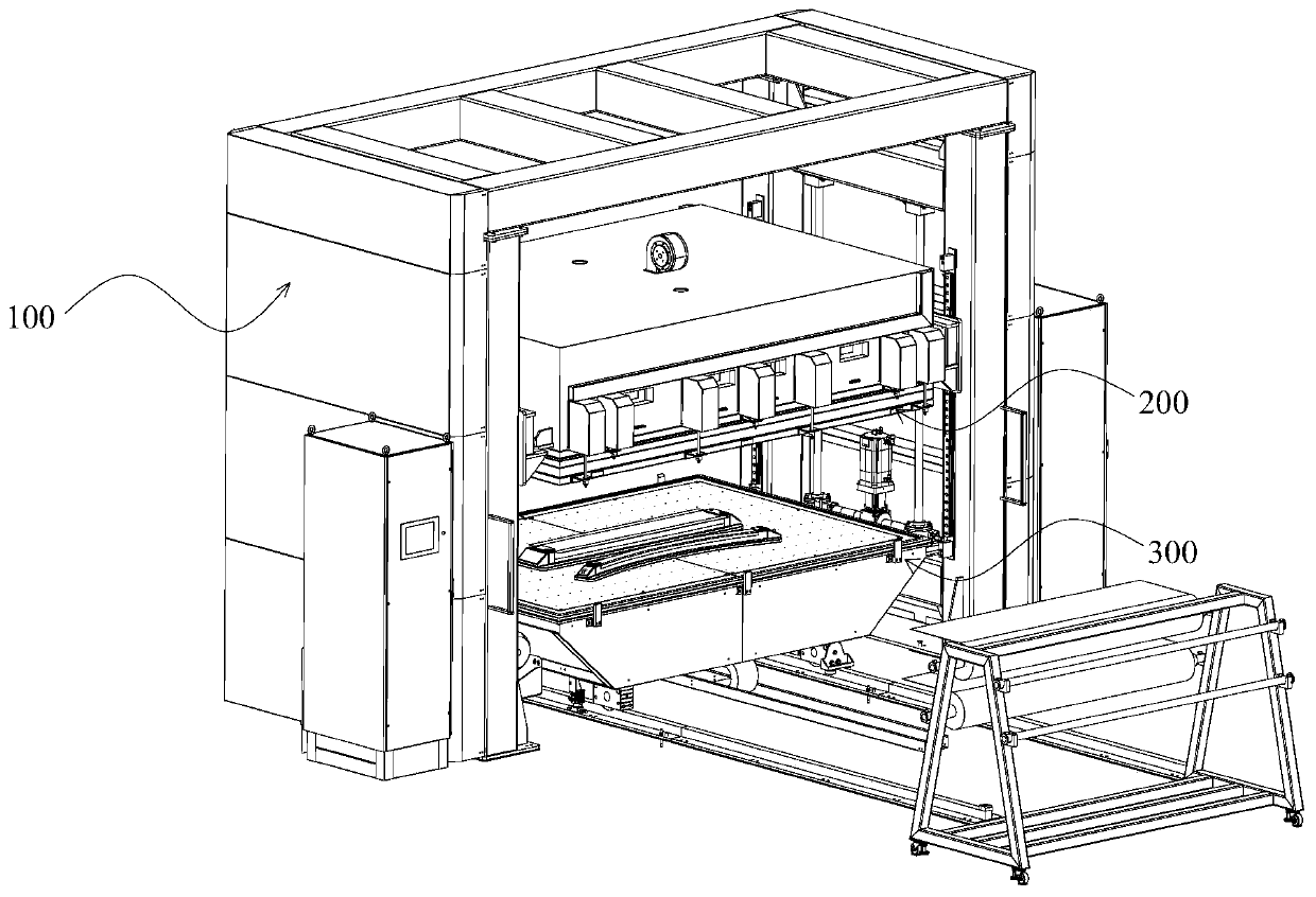
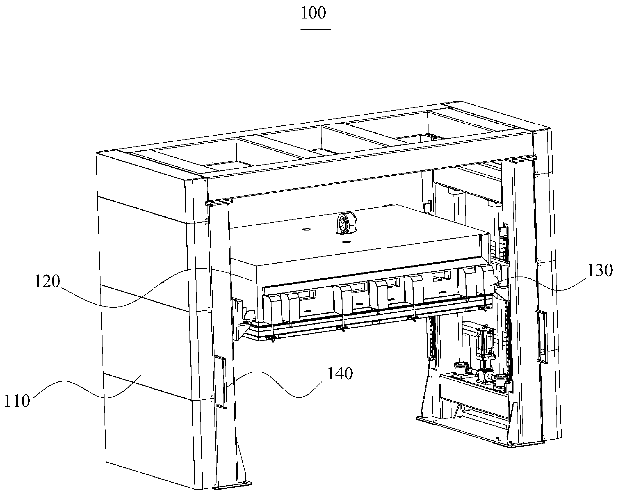
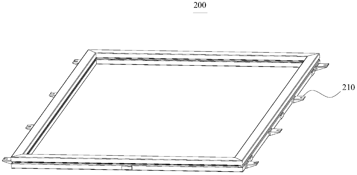
The invention relates to the technical field of heat diaphragm forming, in particular to a heat diaphragm forming system. The system comprises a heating mechanism, a diaphragm frame, and a vacuum bedmechanism. The heating mechanism further comprises a rack, a heating warehouse and a fixing mechanism, the rack is arranged to be of a gantry structure, the heating warehouse is relatively movably mounted in the gantry structure in the height direction, the fixing mechanism is mounted on the heating warehouse, the diaphragm frame is used for fixing a diaphragm, a lifting appliance is mounted on the diaphragm frame, a hanging rod connected with the lifting appliance is mounted on the fixing mechanism, the diaphragm frame can be fixed to the heating warehouse, the vacuum bed mechanism comprisesa horizontal rail mounted towards the rack, a supporting frame capable of being relatively movably mounted on the horizontal rail, a vacuumizing platform fixed to the supporting frame and a vacuum pump connected with the vacuumizing platform, and when the diaphragm frame is not lifted by the fixing mechanism, the diaphragm frame is placed on the vacuumizing platform. Mechanical automation replacesmanpower, and production efficiency is improved.

Description

technical field [0001] The invention relates to the technical field of thermal diaphragm forming, in particular to a thermal diaphragm forming system. Background technique [0002] Thermal diaphragm forming is a composite material forming method, that is, the pre-impregnated composite material is laminated and placed on the mold, and the laminate is pressed to the mold through vacuuming and heating with the assistance of a special diaphragm to form desired shape. [0003] In the prior art, the processing efficiency of thermal diaphragm forming parts is not high. In each step of the thermal diaphragm forming process, too much manual participation is required, such as diaphragm laying and moving, such as vacuuming and heating the mold before of the mobile. [0004] However, on the one hand, the above-mentioned manual operation process will affect the consistency of the product, making it difficult to control the quality of the product. On the other hand, there are also dange...

Claims


Application Information

Patent Timeline
Patent Type & Authority Applications(China)
IPC IPC(8): B29C70/34B29C70/54
CPCB29C70/342B29C70/54
Inventor 谈源谢刚唐海波
Owner NEWTRY COMPOSITE
Learn More