Brake sail deorbiting device applied to vertical satellite

A technology for braking sails and driving devices, applied in the field of spacecraft de-orbit, can solve the problem of space debris affecting the normal operation of other satellites, etc., and achieve the effects of increasing expansion circuits and modular power supplies, expanding area, and simple structure

Inactive Publication Date: 2020-08-28
NANJING UNIV OF SCI & TECH
View PDF9 Cites 3 Cited by
  • Summary
  • Abstract
  • Description
  • Claims
  • Application Information

AI Technical Summary

Problems solved by technology

[0007] The purpose of the present invention is to provide a braking sail deorbiting device applied to cubesats, which is suitable for deorbiting cubesats operating in low and medium orbits, and solves the problem that some cubesats cannot be deorbited within a specified time after completing the task Thus becoming a problem of space debris affecting the normal operation of other satellites

Method used


Image

  • Brake sail deorbiting device applied to vertical satellite
  • Brake sail deorbiting device applied to vertical satellite
  • Brake sail deorbiting device applied to vertical satellite

Examples


Embodiment Construction

[0056] The device will be further described below in conjunction with the accompanying drawings.

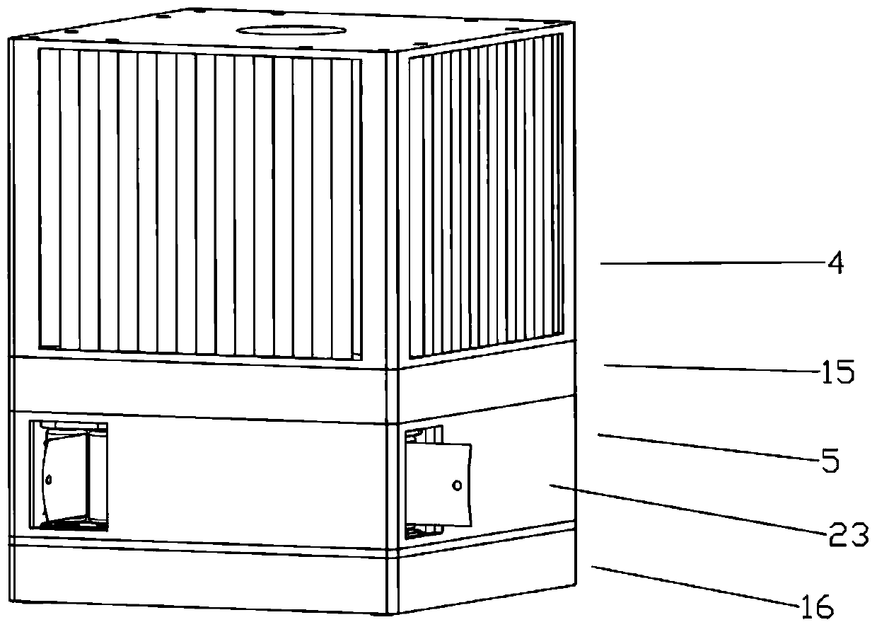
[0057] combine figure 1 , a braking sail deorbiting device applied to a cube star, occupying a space volume of 100mm*100mm*160mm, and from top to bottom are a sail storage device 4, a driving device 15, a deployment device 5 and a locking device 16.

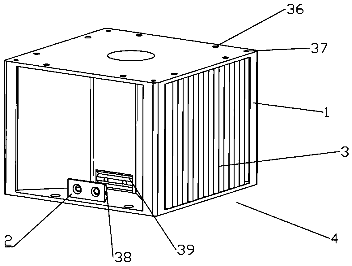
[0058] combine figure 2 , the sail storage device 4 includes a sail storage bin 1, a membrane sail 3 and a membrane sail fixing block 2, the sail storage bin 1 is 4 trapezoidal grooves for storing the membrane sail 3; the center of the sail storage bin 1 is provided with a blind hole To fix the motor that provides power for the device; the film sail fixing block 2 is provided with a through hole, which can be fixed to the sail storage bin 1 through screws, and a corner of the film sail 3 can be fixed on the central structure of the sail storage bin 1; at the same time, for To ensure the reliability of fixing the membrane sail 3, ...


PUM


Abstract

The invention belongs to the field of spacecraft deorbiting, and particularly relates to a brake sail deorbiting device applied to a vertical satellite. The device includes: a sail storage device, a driving device, an unfolding device and a locking device which are sequentially arranged from top to bottom. A film sail is stored in the sail storage device; the unfolding device comprises four strip-shaped elastic masts and a mast center shaft, the extension sections of the strip-shaped elastic masts are connected with the film sail, and the fixed ends of the strip-shaped elastic masts are woundon the mast center shaft; the four wound strip-shaped elastic masts are unfolded to drive the thin film sail connected with the elastic masts to be unfolded; the driving device is used for driving thestrip-shaped elastic mast in the unfolding device to be unfolded; and the locking device is used for locking the unfolding device in a locking state. The deorbiting device provided by the invention is suitable for deorbiting cubesat running on medium and low orbits, and solves the problem that normal work of other satellites is affected by space debris due to the fact that part of cubesat cannotbe deorbited within a specified time after completing a task.

Description

technical field [0001] The invention belongs to the field of spacecraft de-orbiting, and in particular relates to a brake sail de-orbiting device applied to a satellite. Background technique [0002] CubeSat is a CubeSat standard jointly proposed by Caltech and Stanford University in 1999. It is a cube star with standardized volume and shape. The basic unit is a cube of 10cm×10cm×10cm. It is usually called a 1U cube star. After adding the corresponding number of units, it is also called a 2U cube star, 3U cube star, etc., with a simple structure. . [0003] CubeSat has gradually become a research hotspot at home and abroad due to its low cost, short development cycle, and high functional density. It can be seen that in the future, the number of CubeSat launches will grow in a "blowout" style. These cube satellites are usually distributed in low earth orbit. If they are not deorbited after completing their missions, these failed cube satellites will become space debris, res...

Claims


Application Information

Patent Timeline
Patent Type & Authority Applications(China)
IPC IPC(8): B64G1/24B64G1/62
CPCB64G1/242B64G1/62
Inventor 周航黄跃廖文和张翔李佩亭
Owner NANJING UNIV OF SCI & TECH
Why Eureka
Try Eureka