
Rainwater and sewage diverting device for refuse landfill

A waste landfill, rain and sewage diversion technology, applied to water supply devices, sewage discharge, waterway systems, etc., can solve the problems of long field perimeter, long distance of platform drainage ditch, difficult rainwater drainage, etc., to reduce investment, Effect of reducing processing load

Active Publication Date: 2020-09-01
CHINA POWER CONSRTUCTION GRP GUIYANG SURVEY & DESIGN INST CO LTD
View PDF6 Cites 2 Cited by
  • Summary
  • Abstract
  • Description
  • Claims
  • Application Information

AI Technical Summary

Problems solved by technology

[0002] There are two common types of domestic waste landfills, one is valley-type landfill, the other is flat-type landfill, and valley-type landfill is an initial storage capacity formed by natural valleys; when landfill When the landfill site is selected in a narrow and long valley, the bottom area of ​​this landfill site is relatively small, and the site perimeter is long, resulting in a long distance to the platform drainage ditch. Therefore, it will be more difficult to find slopes for drainage. At the same time, as far as the garbage dump is concerned, if the drainage slope is small, it will make it difficult for the rainwater to be drained out, and if the rainwater is not drained smoothly, the sewage within the catchment area of ​​the entire landfill reservoir area will become Leachate, which will undoubtedly greatly increase the processing burden of the landfill leachate treatment station, increase operating costs, and needs to be improved urgently

Method used


Image

  • Rainwater and sewage diverting device for refuse landfill
  • Rainwater and sewage diverting device for refuse landfill
  • Rainwater and sewage diverting device for refuse landfill

Examples


Embodiment Construction

[0039] In order to make the purpose, features and advantages of the present invention more obvious and understandable, the technical solutions in the embodiments of the present invention will be clearly and completely described below in conjunction with the accompanying drawings in the embodiments of the present invention. Obviously, the following The described embodiments are only some, not all, embodiments of the present invention. Based on the embodiments of the present invention, all other embodiments obtained by persons of ordinary skill in the art without making creative efforts belong to the protection scope of the present invention.

[0040] The technical solutions of the present invention will be further described below in conjunction with the accompanying drawings and through specific implementation methods.

[0041] In the description of the present invention, it should be understood that the orientations or positional relationships indicated by the terms "upper", "...


PUM


Abstract

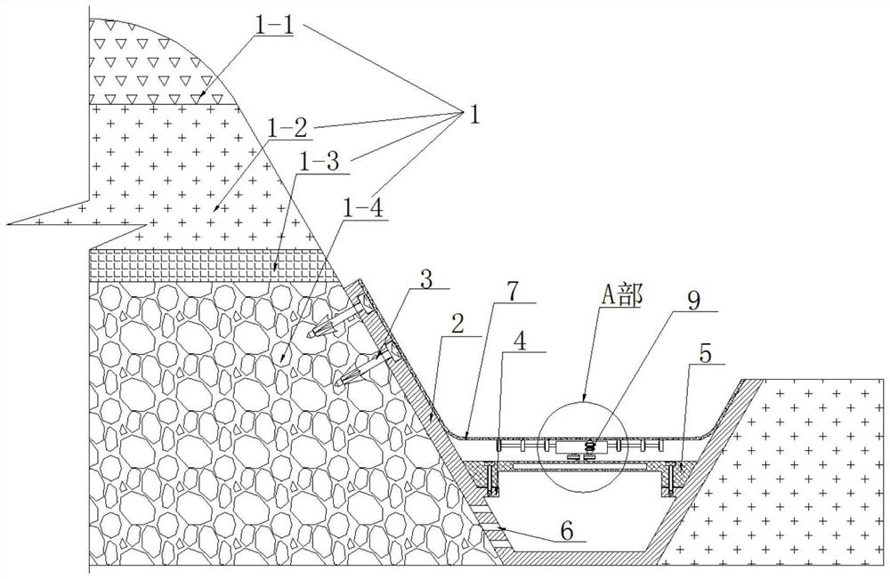
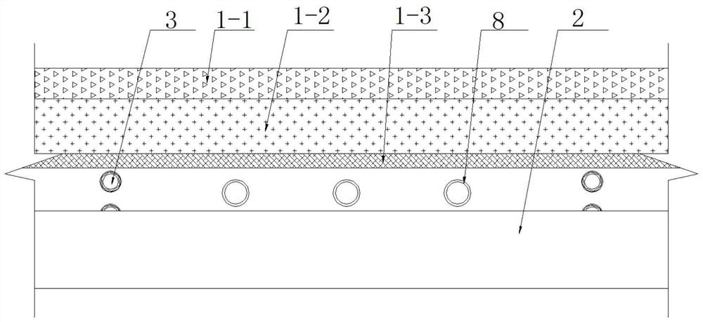
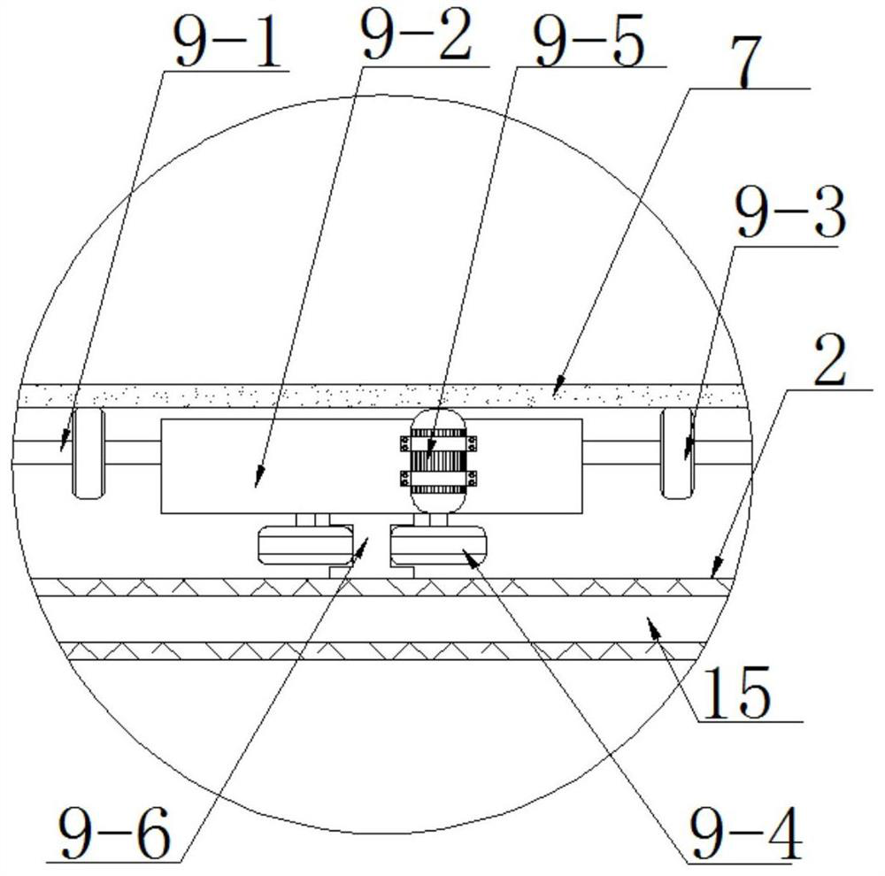
The invention discloses a rainwater and sewage diverting device for a refuse landfill. The device comprises a flow guiding groove, anchor rods, convex blocks, supporting plates, seepage holes, a flowguiding film, a flow guiding pipe and an anti-water-accumulation mechanism. According to the device, part of rainwater falling from the outside penetrates through a greening layer to permeate into anearthwork layer, the other part of rainwater slides onto the flow guiding film in the flow guiding groove from the greening layer, the infiltrated rainwater is blocked through an anti-permeation layer, the rainwater flows into the flow guiding pipe along the anti-permeation layer, and the flow guiding pipe discharges the rainwater into the flow guiding film; and after a period of time of rainwaterand sewage diverting, a driving motor is started, and the output end of the driving motor drives a guiding wheel to advance on a guiding rail, so that a jacking wheel on a rotating shaft jacks the flow guiding film to gradually move towards one side of a gutter inlet, and the accumulated water on the flow guiding film gradually flows towards the gutter inlet until the accumulated water is discharged from the gutter inlet.

Description

technical field [0001] The invention relates to a garbage landfill, in particular to a rainwater and sewage diversion device in the garbage landfill, and belongs to the technical field of infrastructure. Background technique [0002] There are two common types of domestic waste landfills, one is valley-type landfill, the other is flat-type landfill, and valley-type landfill is an initial storage capacity formed by natural valleys; when landfill When the landfill site is selected in a narrow and long valley, the bottom area of ​​this landfill site is relatively small, and the site perimeter is long, resulting in a long distance to the platform drainage ditch. Therefore, it will be more difficult to find slopes for drainage. At the same time, as far as the garbage dump is concerned, if the drainage slope is small, it will make it difficult for the rainwater to be drained out, and if the rainwater is not drained smoothly, the sewage within the catchment area of ​​the entire lan...

Claims


Application Information

Patent Timeline
IPC IPC(8): E03F1/00E03F5/04E03F3/02E03F5/00
CPCE03F1/001E03F3/02E03F5/00E03F5/04
Inventor 孟庆奕陈光耀张小清柯丽静
Owner CHINA POWER CONSRTUCTION GRP GUIYANG SURVEY & DESIGN INST CO LTD
Learn More