
fan blade

A technology of fan blades and blades, which is applied in the field of wind power generation, can solve the problems of unfavorable fan blades running for a long time, the accumulation of stress damage at the connection end, etc., and achieve the effects of reducing the accumulation of stress damage, increasing the service life, and reducing the force difference

Active Publication Date: 2022-01-21
SHANGHAI ELECTRIC WIND POWER GRP CO LTD
View PDF9 Cites 0 Cited by
  • Summary
  • Abstract
  • Description
  • Claims
  • Application Information

AI Technical Summary

Problems solved by technology

In order to facilitate the connection of the two blade segments, the size of the connecting surfaces of the two blade segments of the existing fan blades using segmented blades is the same, but, since the lift coefficient of the blade segment far away from the blade root is greater than that near the The lift coefficient of the blade segment at the root, if the force area near the connecting end of the blade segment away from the root is the same as the force area near the connecting end of the blade segment near the root, then the The force is greater than the force on the connecting end of the blade section near the blade root. The connecting end of the two blade sections bears different forces for a long time, which will cause stress damage accumulation at the connecting end, which is not conducive to the long-term operation of the fan blade.

Method used


Image

  • fan blade
  • fan blade
  • fan blade

Examples


Embodiment Construction

[0053] The present invention will be further described below by means of specific examples, but the present invention is not limited to the scope of the following examples.

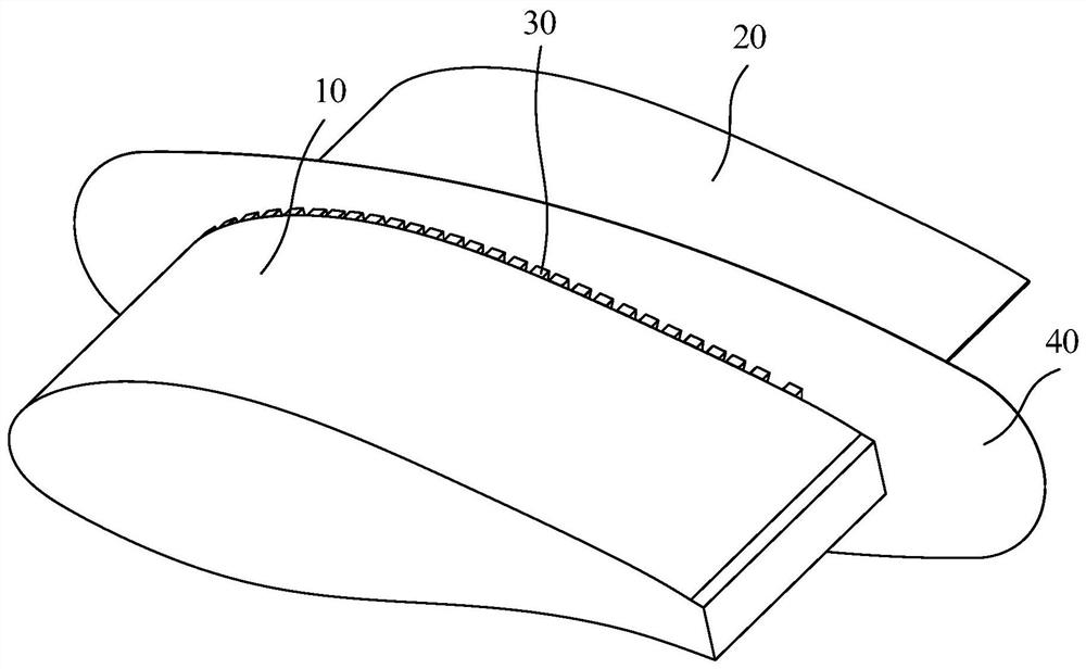
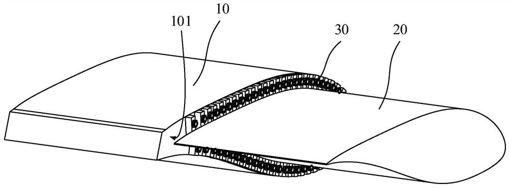
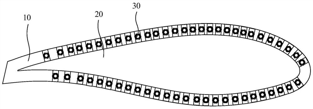
[0054] like Figure 1-4 As shown, it is a fan blade of this embodiment, and the fan blade includes a first blade section 10 and a second blade section 20, the first blade section 10 is arranged closer to the blade root of the fan blade relative to the second blade section 20, and the second blade section 20 is arranged closer to the blade root of the fan blade. The first blade section 10 and the second blade section 20 have oppositely arranged first connecting surface 101 and second connecting surface 201 respectively, and the chord length of the blade airfoil section at the second connecting surface 201 is smaller than that at the first connecting surface 101. The chord length of the section. Wherein, the blade airfoil section refers to the cross section of the blade perpendicular to the leading edge of...


PUM


Abstract

The invention discloses a fan blade, the fan blade includes a first blade section and a second blade section, the first blade section is arranged closer to the blade root of the fan blade relative to the second blade section, the The first blade section and the second blade section respectively have a first connection surface and a second connection surface oppositely arranged, and the chord length of the blade airfoil section at the second connection surface is smaller than that of the blade at the first connection surface The chord length of the wing section. In the fan blade of the present invention, since the chord length of the blade airfoil section at the second connection surface is smaller than the chord length of the blade airfoil section at the first connection surface, the force-bearing area of ​​the blade end at the second connection surface is smaller than that at the first connection surface. The stress-bearing area of ​​the blade end can reduce the force difference generated at the joint of the two blade segments, thereby reducing the accumulation of stress damage and improving the service life of the blade.

Description

technical field [0001] The invention relates to the field of wind power generation, in particular to a fan blade. Background technique [0002] According to the cost of power generation, the larger the design power of a single wind turbine, the lower the LCOE (levelized cost of electricity). However, high-power wind turbines often mean super-long blades, and the transportation of super-long blades is very difficult, especially for curved mountain roads with complex terrain. It is more difficult to transport large blades, which greatly increases the transportation cost and the operation and maintenance cost of the blades. It accounts for a part that cannot be ignored in the cost of the whole machine. Effectively reducing the transportation cost of the blades is not only beneficial to the cost reduction of wind turbines, but also becomes more and more important to the grid parity. In this case, large wind turbine blades are manufactured, transported and On-site installation. ...

Claims


Application Information

Patent Timeline
Patent Type & Authority Patents(China)
IPC IPC(8): F03D1/06
CPCF03D1/0675F03D1/0633F03D1/0641Y02E10/72
Inventor 罗红王国军许移庆
Owner SHANGHAI ELECTRIC WIND POWER GRP CO LTD
Learn More