Flow regulating valve

A flow control valve and flow rate technology, which is applied in the field of flow control valves for regulating refrigerant flow, can solve problems such as easy occurrence and growth, refrigerant peeling, pressure changes, etc., to achieve smooth flow, small pressure loss, and suppress pressure changes Effect

Active Publication Date: 2020-09-01
FUJIKOKI MFG CO LTD
View PDF12 Cites 2 Cited by
  • Summary
  • Abstract
  • Description
  • Claims
  • Application Information

AI Technical Summary

Problems solved by technology

[0009] Among the flow regulating valves 1' formed in such a way as to obtain equal percentage characteristics, such as Figure 5 As shown by the bold arrow, when the flow direction of the refrigerant is from the valve chamber 6 to the valve port 15, the flow of the refrigerant along the curved surface 23 is prone to rapid pressure changes and refrigerant peeling when passing through the valve port 15. , vortex and cavitation are prone to occur and grow, while the problem of larger noise occurs

Method used


Image

  • Flow regulating valve
  • Flow regulating valve
  • Flow regulating valve

Examples


Embodiment Construction

[0039] Hereinafter, specific embodiments of the present invention will be described with reference to the drawings.

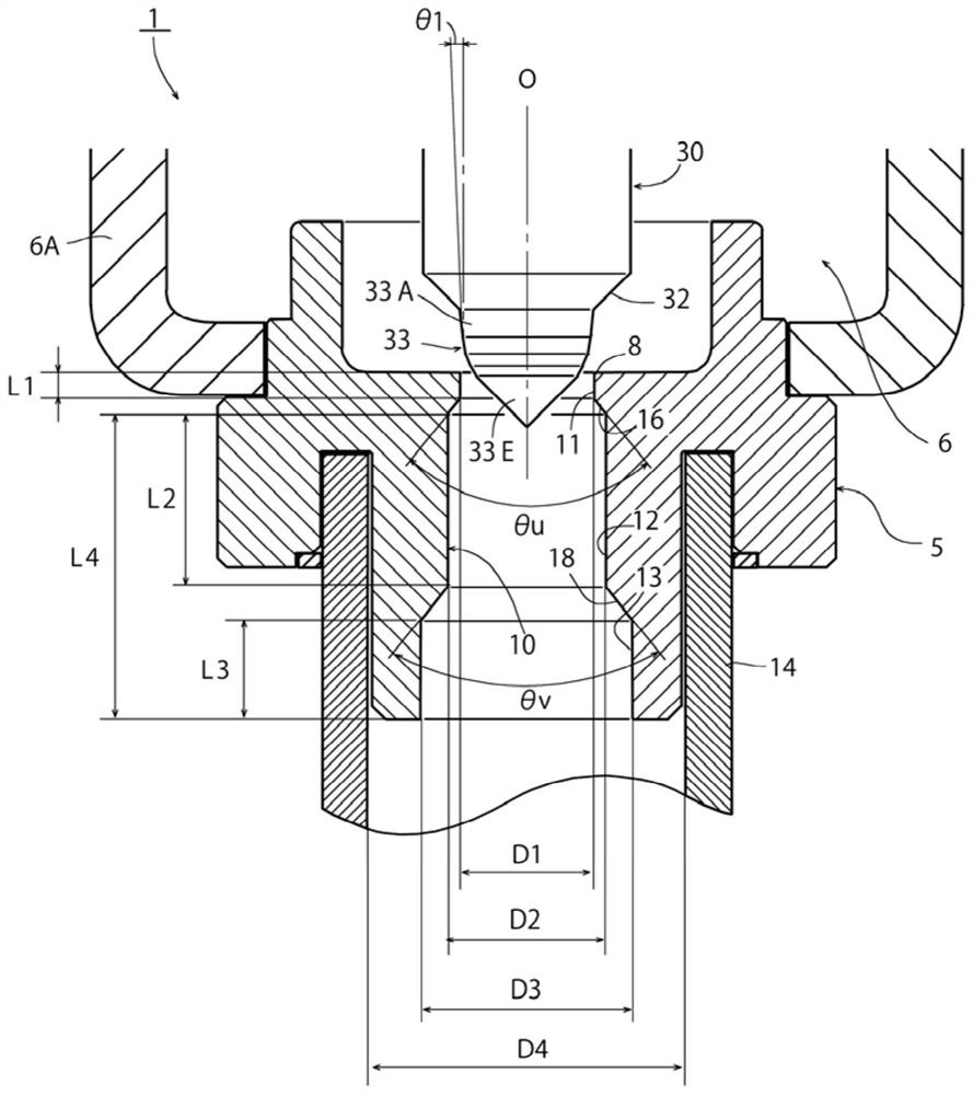
[0040] figure 1 It is a cross-sectional view showing an essential part of an embodiment of the flow control valve according to the present invention. In addition, in figure 1 , for the above Figure 6A , Figure 6B The parts corresponding to the respective parts of the shown conventional flow regulating valve 1" are given the same reference numerals.

[0041] The flow regulating valve 1 of the illustrated embodiment is the same as the above-mentioned Figure 6A , Figure 6B The conventional flow control valve 1" shown is similarly formed in such a manner as to obtain characteristics similar to the equal percentage characteristic, and includes: a valve main body 5 to which a valve chamber forming member 6A is fixed, and is provided as the main body. The valve port 10 (described later in detail) of the characteristic part of the invention; and the valve cor...


PUM


Abstract

The invention provides a flow regulating valve which can effectively reduce the noise generated due to a pressure fluctuation and a refrigerant separation phenomenon during passage through a valve port, and can achieve reduction of a pressure loss and so forth. The flow regulating valve 1 comprises a valve body 5 provided with a valve chamber 6 and a valve port 10, and a valve element 30 having acurved surface part 33 which changes the flow rate of fluid flowing through the valve port 10 according to a lift amount, in which the curvature or the control angle of the curved surface part 33 is continuously or stepwisely increased according as getting close to the end. The diameter of the valve port 10 is increased sequentially in three stages or more according as being separated from the valve chamber 6. Specifically, sequentially from the valve chamber 6 side, a first valve port part 11 having a diameter D1, a second valve port part 12 of diameter D2 (>D1) and a third valve port part 13of a diameter D3 (>D2) are provided. More preferably, D1, D2 and D3 are set such that (a valve port ratio: D2 / D1) and (a valve port ratio: D3 / D2) fall in a specific range.

Description

[0001] This application is a divisional application of the following patent application: [0002] Application number: 201611009696.X [0003] Application date: November 16, 2016 [0004] Invention name: flow control valve technical field [0005] The present invention relates to a flow regulating valve provided with a valve main body provided with a valve chamber and an orifice, and a valve core that changes the flow rate of the fluid flowing through the orifice according to the lift, and particularly relates to a heat pump type valve. A flow regulating valve suitable for regulating the flow of refrigerant in refrigeration and heating systems, etc. Background technique [0006] As the relationship between the valve opening (lift) and the flow rate of the flow regulating valve, that is, the flow characteristic, the linear characteristic and the equal percentage characteristic are well known. The linear characteristic refers to the characteristic that the change rate of the...

Claims


Application Information

Patent Timeline
Patent Type & Authority Applications(China)
IPC IPC(8): F16K1/36F16K1/42F16K1/54F16K47/02
CPCF16K1/36F16K1/42F16K1/54F16K47/02F25B2500/12F25B41/35
Inventor 菅沼威猪野泰利大森绘理
Owner FUJIKOKI MFG CO LTD
Why Eureka
Try Eureka