Water draining system with gas double-wall pipe

A technology of drainage system and double-wall pipe, applied in the direction of pipeline system, pipe, rigid pipe, etc., can solve problems such as fire and gas discharge into the engine room, and achieve the effect of preventing gas from entering the engine room.

Inactive Publication Date: 2020-09-01
GUANGZHOU WENCHONG SHIPYARD CO LTD
View PDF9 Cites 3 Cited by
  • Summary
  • Abstract
  • Description
  • Claims
  • Application Information

AI Technical Summary

Problems solved by technology

[0005] In view of the above problems, the purpose of the present invention is to provide a gas double-wall pipe drainage system, which can solve the problem of direct discharge of condensed water to the engine room in the prior art. When there is damage between the inner and outer pipes of the double-wall pipe, the gas may also be discharged into the engine room, thereby posing a fire hazard technical problem

Method used


Image

  • Water draining system with gas double-wall pipe
  • Water draining system with gas double-wall pipe
  • Water draining system with gas double-wall pipe

Examples


Embodiment 1

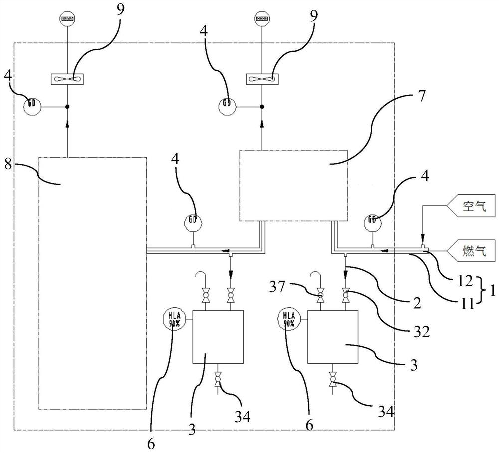
[0029] Such as Figure 1 to Figure 4 As shown, a gas double-wall pipe 1 drainage system described in the embodiment of the present invention includes a gas double-wall pipe 1, and a main engine gas valve group 7 and a The dual-fuel main engine 8, the air outlet of the main engine gas valve group 7, and the air outlet of the dual-fuel main engine 8 are all connected to the exhaust fan 9 through the ventilation pipe; the gas double-wall pipe 1 includes an outer pipe 11 and an inner pipe 12, and the inner pipe 12 The air inlet of the pipe 12 is connected to the gas inlet; a discharge pipe 2 is connected at the lowest point of each pipe body bend of the outer pipe 11; A combustible gas detection device 4 is provided on the connecting pipe section of the pipe 2;

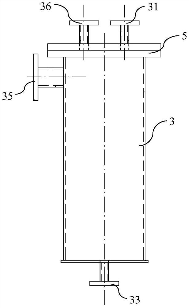
[0030] A discharge pipe 2, the water outlet of the discharge pipe 2 is connected to the water inlet 31 of the discharge tank 3;

[0031] The discharge tank 3, the water inlet 31 of the discharge tank 3 is equipped with ...

Embodiment 2

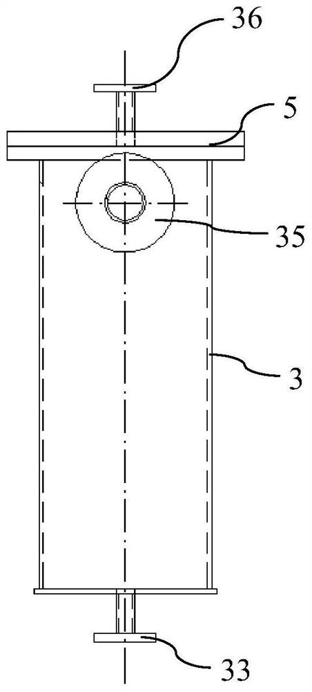
[0042] Such as Figure 5 As shown, the difference between the gas double-wall pipe 1 drainage system provided in this embodiment and the first embodiment is that the number of the discharge tank 3 is one, and the water outlet of each discharge pipe 2 is connected to the Describe the water inlet 31 of the discharge tank 3.

[0043] To sum up, the drainage system of the gas double-wall pipe 1 according to the present invention can be kept open by controlling the first stop valve 32, so that the condensed water in the outer pipe 11 can be directly discharged into the discharge tank 3, In this way, the condensed water avoids blocking the outer pipe 11; in addition, before opening the second shut-off valve 34 to discharge the condensed water in the drain tank 3 to the engine room sewage well, first confirm whether the combustible gas detection device 4 is Trigger an alarm response, if an alarm response occurs, then first close the air inlet of the inner pipe 12, and simultaneously...


PUM


Abstract

The invention discloses a water draining system with a gas double-wall pipe. The system comprises the gas dual-wall pipe, draining pipes and a draining tank, the gas dual-wall pipe comprises an outerpipe and an inner pipe, the draining pipes are connected to the lowest points of all pipe body bending positions of the outer pipe, combustible gas detection devices are arranged on connecting pipe segments of the outer pipe and the draining pipes, water outlets of the draining pipes are connected with a water inlet of the draining tank, the water inlet of the draining tank is provided with a first stop valve in a matched manner, the first stop valve is used for controlling the water inlet of the draining tank to be opened or closed, a draining opening is formed in the bottom of the draining tank, and is provided with a second stop valve in a matched manner, and the second stop valve is used for controlling the draining opening to be opened or closed. According to the water draining systemwith the gas double-wall pipe, the technical problems that in the prior art, condensate water is directly drained to a cabin, when the position between the inner pipe and the outer pipe of the dual-wall pipe is damaged, gas is possibly exhausted into the cabin, and the fire danger is caused can be solved.

Description

technical field [0001] The invention relates to the technical field of drainage systems, in particular to a gas double-wall pipe drainage system. Background technique [0002] Dual-fuel container ships usually use oil and gas as the fuel for the main engine, main generator set and boiler. The International Code for the Construction and Equipment of Ships Carrying Liquefied Gases in Bulk (IGC CODE) stipulates that when gas is used as fuel, the area inside the engine room must use double-wall pipes as the delivery pipeline, otherwise the engine room will be defined as a hazardous area. [0003] The double-wall pipe has two layers, the inner pipe and the outer pipe. The medium of the inner pipe is gas, and the temperature of the gas entering the engine room is about 0°C. The medium of the outer tube is the air from the outside of the ship, and the outer tube is connected to the exhaust fan to continuously suck the air out of the outer tube through the exhaust fan, so that the ...

Claims


Application Information

Patent Timeline
Patent Type & Authority Applications(China)
IPC IPC(8): F17D1/00F17D5/02F17D5/06F16L9/18
CPCF16L9/18F17D1/00F17D5/02F17D5/06Y02T10/30
Inventor 陈俊耿李勇杰许炜麟
Owner GUANGZHOU WENCHONG SHIPYARD CO LTD
Why Eureka
Try Eureka