
Lighting device

A lighting device, Rayleigh scattering technology, applied in lighting devices, non-electric lighting devices, fixed lighting devices, etc., can solve the problem that sky lights cannot simulate the characteristics of sunlight irradiation

Pending Publication Date: 2020-09-01
QINGDAO YEELINK INFORMATION TECH
View PDF0 Cites 4 Cited by
  • Summary
  • Abstract
  • Description
  • Claims
  • Application Information

AI Technical Summary

Problems solved by technology

[0005] The main purpose of the present invention is to provide a lighting device to solve the technical problem that the sky lamp in the prior art cannot simulate the irradiation characteristics of sunlight.

Method used


Image

  • Lighting device
  • Lighting device
  • Lighting device

Examples


Embodiment Construction

[0036] It should be noted that, in the case of no conflict, the embodiments in the present application and the features in the embodiments can be combined with each other. The present invention will be described in detail below with reference to the accompanying drawings and examples.

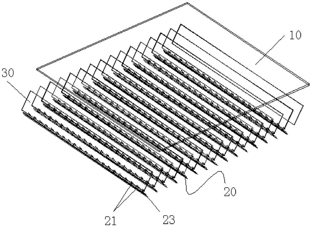
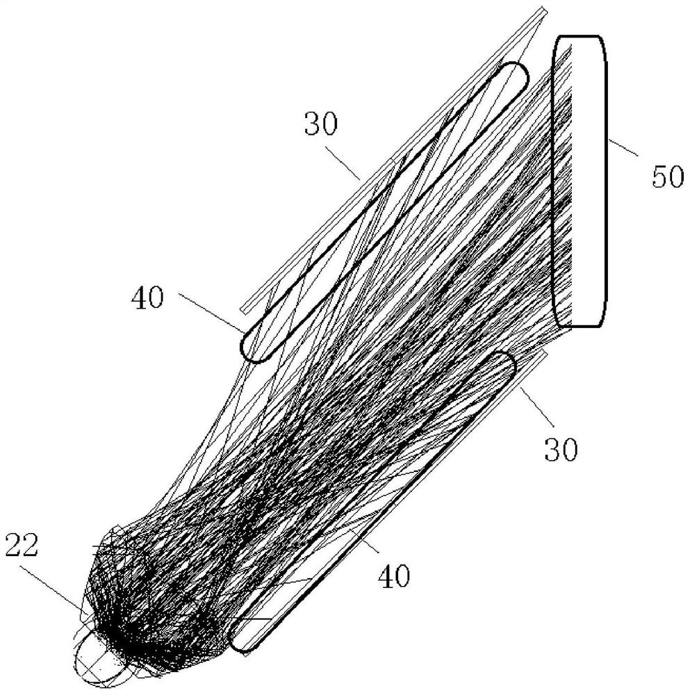
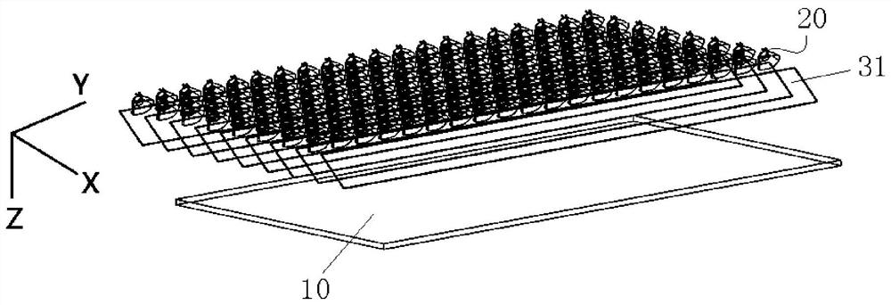
[0037] Such as Figure 1 to Figure 10 As shown (a space Cartesian coordinate system is established in some figures, with mutually perpendicular X-axis, Y-axis and Z-axis), the embodiment of the present invention provides a lighting device, which includes a Rayleigh scattering plate 10, a light emitting The component 20 and the light shielding portion 30, the Rayleigh scattering plate 10 have a light incident surface and a light exit surface oppositely arranged. The light-emitting assembly 20 is arranged opposite to the light incident surface. The light-emitting assembly 20 includes a light-emitting part 21 and a total reflection lens 22. The light-emitting part 21 is arranged obliquely relativ...


PUM


Abstract

The invention provides a lighting device which comprises the components of a Rayleigh scattering board, a light-emitting assembly and a shading part. The Rayleigh scattering board is provided with a light incident surface and a light emergent surface that are oppositely arranged; the light-emitting assembly is arranged opposite to the light incident surface, the light-emitting assembly comprises alight-emitting part and a total reflection lens, the light-emitting part is obliquely arranged relative to the Rayleigh scattering board, and the total reflection lens is arranged at the light-emitting part and used for reducing the emergent angle of a light beam emitted by the light-emitting part; and the shading part is arranged between the Rayleigh scattering board and the light-emitting assembly so as to shade the light-emitting assembly through the shading part. According to the technical scheme provided by the invention, the technical problem that a sky lamp in the prior art cannot simulate the irradiation characteristics of irradiation light of sunlight can be solved.

Description

technical field [0001] The present invention relates to the technical field of lighting devices, in particular to a lighting device. Background technique [0002] At present, a new form of lighting has emerged in the home lighting industry - sky lights, or blue sky lights. Sky lights in the prior art generally have two modes, one of which is mainly used to simulate the visual effect of the sky. This sky light generally includes LED lights and Rayleigh scattering plates, and the outgoing light from the LED lights comes from When the two ends of the Rayleigh scattering plate are incident, the light in the Rayleigh scattering plate will undergo the Rayleigh scattering effect, a part of the light will travel randomly in the Rayleigh scattering plate, and finally dissipate in the Rayleigh scattering plate, and the other part of the light will pass through the Rayleigh scattering plate. The light exit surface of the Rayleigh scattering plate exits at a large angle. [0003] Howe...

Claims


Application Information

Patent Timeline
IPC IPC(8): F21S8/04F21V5/00F21V5/04F21V1/00F21V19/00F21V11/02F21V11/06F21V7/00F21V7/04F21Y115/10
CPCF21S8/04F21V5/002F21V5/04F21V1/00F21V19/001F21V19/003F21V11/02F21V11/06F21V7/0091F21V7/04F21Y2115/10
Inventor 王国建姜兆宁刘达平魏巍
Owner QINGDAO YEELINK INFORMATION TECH
Learn More