Adjustable twist drill grinding device

A twist drill and adjustable technology, applied in twist drills, grinding drive devices, grinding machines, etc., can solve the problems of low sharpening efficiency, increased friction between the tool and the workpiece, high drilling torque, and high cost of machine tools to achieve improved edge Grinding efficiency, simplification of forming movement, and reduction of technical requirements

Pending Publication Date: 2020-09-04
SHAANXI SCI TECH UNIV
View PDF0 Cites 4 Cited by
  • Summary
  • Abstract
  • Description
  • Claims
  • Application Information

AI Technical Summary

Problems solved by technology

CNC sharpening is mostly processed by multi-axis CNC grinding machines imported from abroad, the cost of machine tools is high, and the operator's technical requirements are high; the quality of manual sharpening depends on the technical level and experience of the operator, and the sharpening accuracy is difficult to guarantee , high labor intensity, poor cutting edge symmetry; grinding on universal tool grinder, the structure of the grinding device is complex, and there are many forming movements, the adjustment of the machine tool is more cumbersome, the efficiency of sharpening is low, and there are few practical applications
[0005] In addition, improper selection of sharpening parameters can easily lead to "tail lift" on the flank of the drill bit
During drilling, the "tail lift" of the drill reduces the gap between the flank of the drill and the workpiece processing surface, increases the friction between the tool and the workpiece and the drilling torque, reduces the drilling quality, and even As a result, the drilling process cannot be carried out smoothly, and the drill bit is broken

Method used


Image

  • Adjustable twist drill grinding device
  • Adjustable twist drill grinding device
  • Adjustable twist drill grinding device

Examples


Embodiment Construction

[0033] In order to make the object, technical solution and advantages of the present invention clearer, the present invention will be further described in detail below in conjunction with the accompanying drawings and embodiments. It should be understood that the specific embodiments described here are only used to explain the present invention, not to limit the present invention.

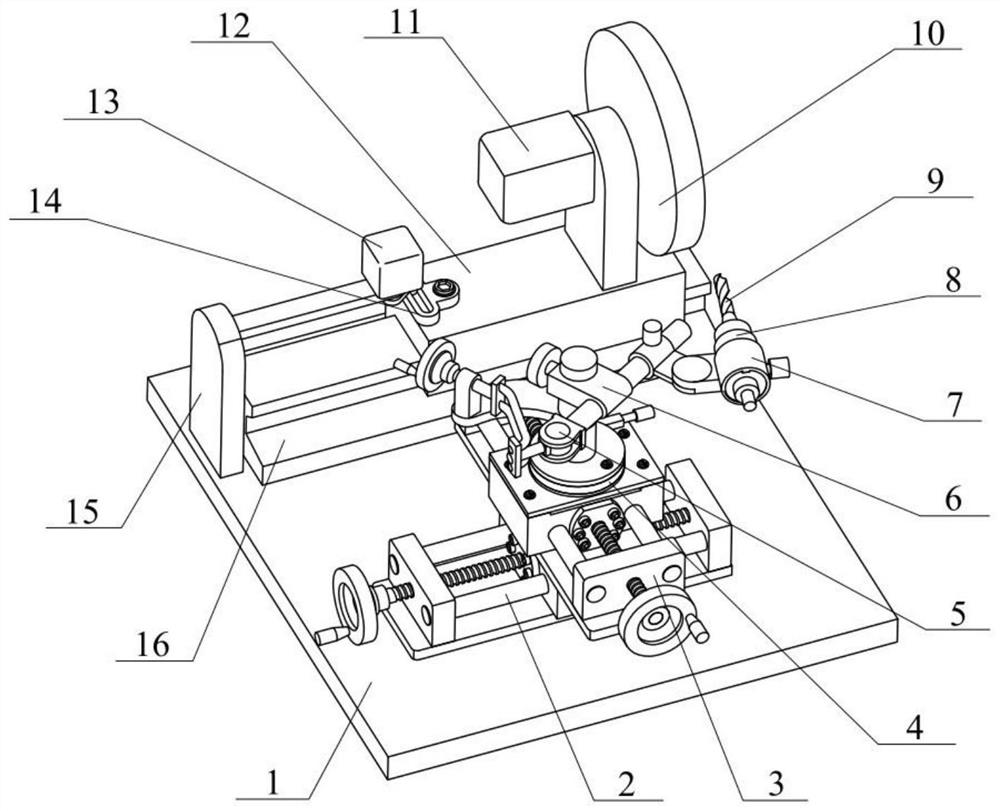
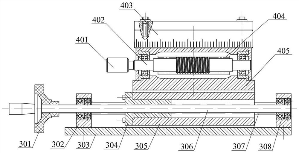
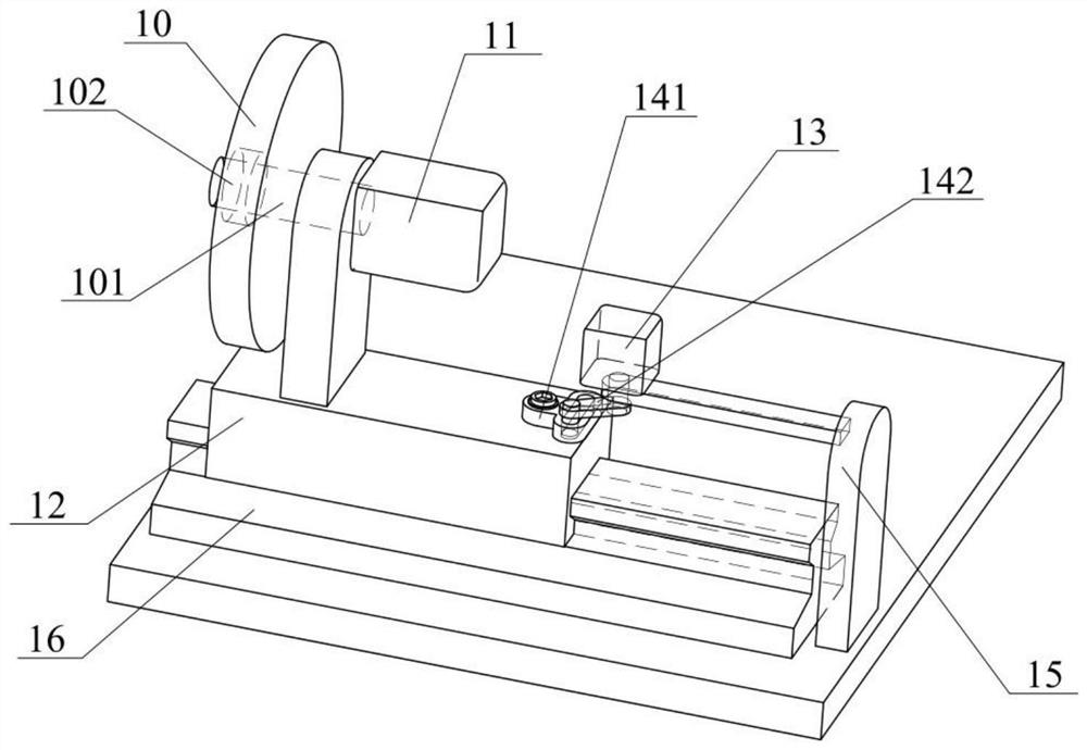
[0034] Embodiments of the present invention provide an adjustable twist drill grinding device, such as Figure 1-5 As shown, it includes a horizontal base 1, a horizontal sliding rail mechanism 2, a vertical horizontal sliding rail mechanism 3, a rotary table 4, a sharpening transmission mechanism 5, a vertical sliding mechanism 6, a clamping mechanism 7, a drill chuck 8, Twist drill 9, grinding wheel grinding mechanism, the horizontal base 1 is superimposed on the horizontal horizontal sliding guide rail mechanism 2, the longitudinal horizontal sliding guide rail mechanism 3, the rotary table 4 is...


PUM


Abstract

The invention discloses an adjustable twist drill grinding device. The adjustable twist drill grinding device comprises a horizontal base, a transverse horizontal sliding guide rail mechanism, a longitudinal horizontal sliding guide rail mechanism, a rotary workbench, a cutter grinding transmission mechanism, a vertical sliding mechanism, a clamping mechanism, a drill chuck, a twist drill and a grinding wheel grinding mechanism, wherein the transverse horizontal sliding guide rail mechanism and the longitudinal horizontal sliding guide rail mechanism are arranged on the horizontal base in a cross-shaped overlaying mode; the rotary workbench is arranged on the longitudinal horizontal sliding guide rail mechanism and used for moving in the longitudinal and transverse directions in the horizontal plane along with the transverse horizontal sliding guide rail mechanism and the longitudinal horizontal sliding guide rail mechanism; the cutter grinding transmission mechanism is arranged on therotary workbench and connected with the clamping mechanism through the vertical sliding mechanism; the clamping mechanism is connected with the drill chuck; the drill chuck is used for mounting the twist drill; and the grinding wheel grinding mechanism is arranged on one side of the horizontal base.

Description

technical field [0001] The invention belongs to the field of tool manufacturing, and in particular relates to an adjustable twist drill grinding device. Background technique [0002] Twist drill is the most commonly used hole processing tool, which is widely used in automobile manufacturing, aerospace and medical equipment and other fields. Compared with other hole processing tools, the complex drill tip structure of twist drill has always been a difficult point in tool manufacturing; With the increasing application of difficult-to-machine materials such as nickel-based high-temperature alloys, stainless steel, titanium alloys, and fiber composites in the manufacture of modern machinery and equipment, it has aggravated the tool wear and damage of the drill bit flank during the drilling process, and shortened the tool life. The service life is shortened, the replacement frequency of new knives is accelerated, and the manufacturing cost of parts is greatly increased. [0003]...

Claims


Application Information

Patent Timeline
Patent Type & Authority Applications(China)
IPC IPC(8): B24B3/26B24B41/06B24B41/02B24B47/12B24B27/02
CPCB24B3/247B24B3/26B24B27/02B24B41/02B24B47/12
Inventor 白海清沈钰高飞安熠蔚
Owner SHAANXI SCI TECH UNIV
Why Eureka
Try Eureka