Heat collection type reactor with high heat utilization rate and working method of heat collection type reactor

A reactor and utilization rate technology, applied in the field of thermal collectors, can solve problems such as unfavorable light-to-heat conversion, and achieve the effects of increasing heat exchange area, large heat transfer coefficient, and high heat utilization rate

Pending Publication Date: 2020-09-04
SUZHOU BEIKAI BIOCHEM EQUIP
View PDF0 Cites 0 Cited by
  • Summary
  • Abstract
  • Description
  • Claims
  • Application Information

AI Technical Summary

Problems solved by technology

[0006] Purpose of the invention: In order to overcome the above deficiencies, the purpose of the present invention is to provide a thermal collector reactor with high heat utilization rate, which solves the great limitations of the fixed structure of the light reflection plate in the prior art, which is not conducive to light-to-heat conversion The problem

Method used


Image

  • Heat collection type reactor with high heat utilization rate and working method of heat collection type reactor
  • Heat collection type reactor with high heat utilization rate and working method of heat collection type reactor
  • Heat collection type reactor with high heat utilization rate and working method of heat collection type reactor

Examples


Embodiment 1

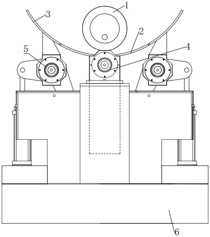
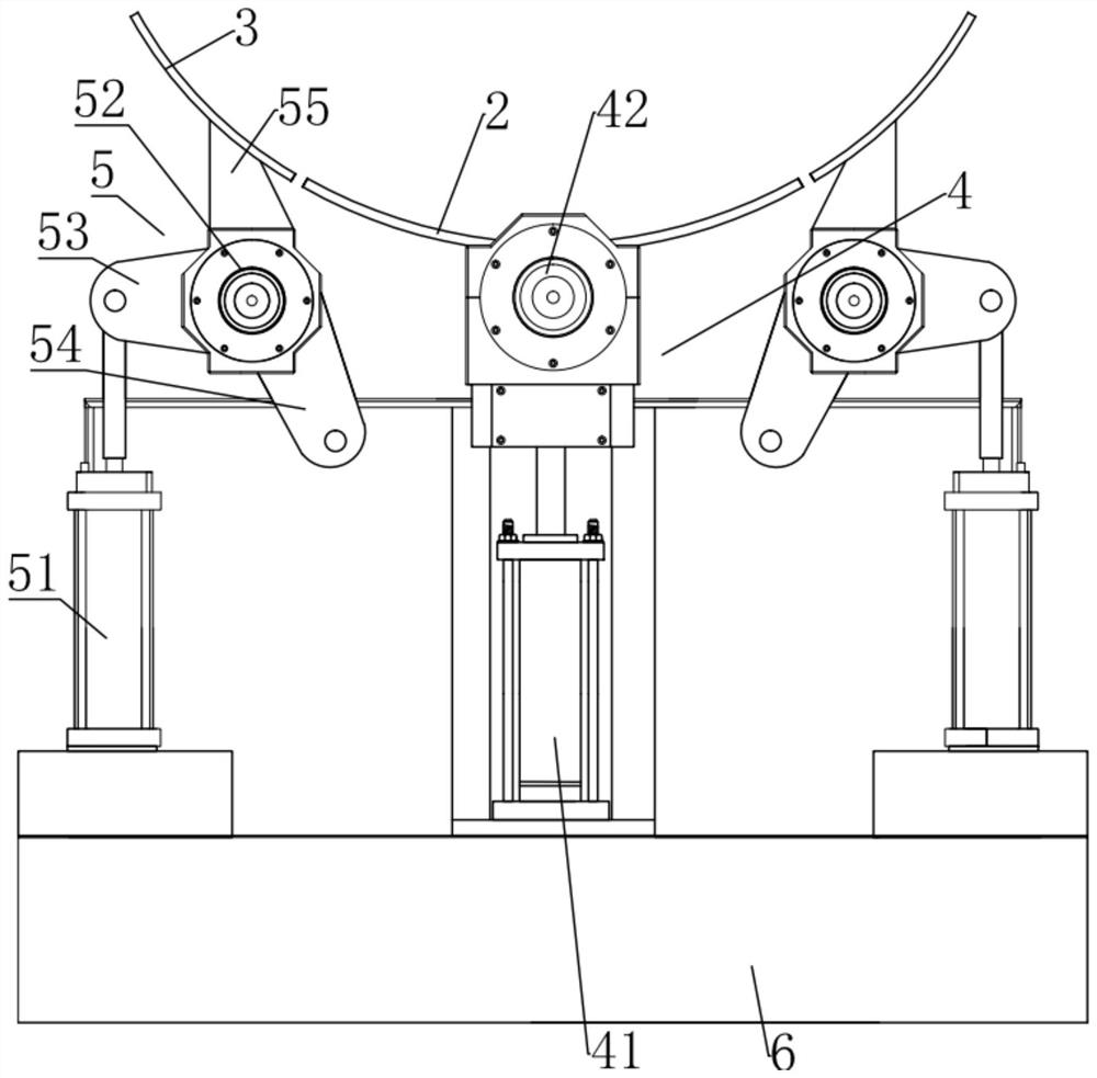
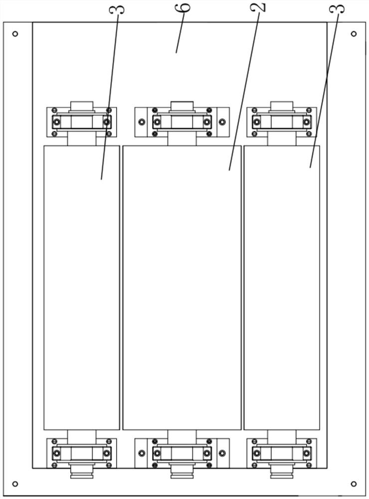
[0045] Such as Figure 1-6 The heat-collecting reactor with high heat utilization rate shown includes reactor 1, condenser mirror 1 2, two symmetrically arranged condenser mirrors 2 3, condenser mirror 1 height adjustment device 4, and two symmetrically arranged condenser mirrors 2 Angle adjustment device 5 and support platform 6, described concentrating mirror surface one height adjustment device 4, two concentrating mirror surface two angle adjustment devices 5 and reactor 1 that are arranged symmetrically are all arranged on the support platform 6, and described concentrating mirror surface one 2 is provided with On the converging mirror surface one height adjusting device 4, the concentrating mirror surface two 3 is arranged on the concentrating mirror surface two angle adjustment device 5, and the two concentrating mirror surfaces two 3 that are symmetrically arranged are respectively arranged on the both sides of the concentrating mirror surface one 2, and the Condensing...

Embodiment 2

[0049] Based on the structure of Embodiment 1, such as Figure 7 , 8 The shown reactor 1 includes a metal heat absorbing tube 10, a vacuum heat collecting tube 11, a glass tube 12, two symmetrically arranged adapters 13, two symmetrically arranged metal expansion joints 14, a high temperature molten salt 15, and a set of reaction Thin tube 16, two symmetrically arranged connecting plates 17, liquid inlet joint 18 and liquid outlet joint 19, the vacuum heat collecting tube 11 is set outside the glass tube 12, and the glass tube 12 is set on the metal heat absorbing The outside of the tube 10, and the two ends of the metal heat absorbing tube 10 along the axis protrude from the glass tube 12, the metal heat absorbing tube 10 and the glass tube 12 are coaxially arranged, and the two symmetrically arranged metal expansion tube joints 14 are respectively arranged at both ends of the glass tube 12, and the metal expansion joint 14 and the glass tube 12 are fixedly connected through...


PUM


Abstract

The invention discloses a heat collection type reactor with a high heat utilization rate and a working method. The heat collection type reactor comprises a reactor, a condensing mirror surface I, twosymmetrically-arranged condensing mirror surfaces II, a condensing mirror surface I height adjusting device, two symmetrically-arranged condensing mirror surface II angle adjusting devices and a supporting platform. According to the heat collection type reactor with the high heat utilization rate, the distance between the condensing mirror surface I and the reactor can be adjusted through the arranged condensing mirror surface I height adjusting device, so that the position between the reactor and the condensing mirror surface I can be adjusted according to different positions and time periods, and an optimal heat collection effect is achieved; the two symmetrically-arranged condensing mirror face II angle adjusting devices work independently so as to adjust the angles of the two symmetrically-arranged condensing mirror faces II respectively. The device is suitable for illumination in different time periods, and the optimal working efficiency is achieved.

Description

technical field [0001] The invention belongs to the field of chemical equipment, in particular to a heat collecting reactor with high heat utilization rate. The invention also relates to a working method of a thermal collecting reactor with high heat utilization rate. Background technique [0002] Temperature control and stirring are important operations in scientific research and production in many fields, and they often need to be carried out simultaneously in applications. At present, a variety of integrated temperature control and stirring equipment have been developed, and have been widely used in various colleges and universities, environmental protection, scientific research, health and epidemic prevention stations, petroleum, chemical, medical and other units. It is a modern chemical, chemical, material, etc. , biology and other laboratory necessary equipment. [0003] Solar energy is a natural energy with huge reserves, wide sources, no pollution, and low cost. Th...

Claims


Application Information

Patent Timeline
Patent Type & Authority Applications(China)
IPC IPC(8): F24S10/40F24S10/75F24S23/70F24S60/30F24S80/20
CPCF24S10/40F24S10/75F24S23/70F24S60/30F24S80/20Y02E10/44
Inventor 毛建民
Owner SUZHOU BEIKAI BIOCHEM EQUIP
Why Eureka
Try Eureka