Intelligent digital chip delivery detection device
A digital chip and factory inspection technology, applied in the direction of measuring devices, measuring electricity, measuring electrical variables, etc., can solve the problems of low manual operation efficiency and achieve the effect of improving detection efficiency
- Summary
- Abstract
- Description
- Claims
- Application Information
AI Technical Summary
Problems solved by technology
Method used
Image

Examples
specific Embodiment approach 1
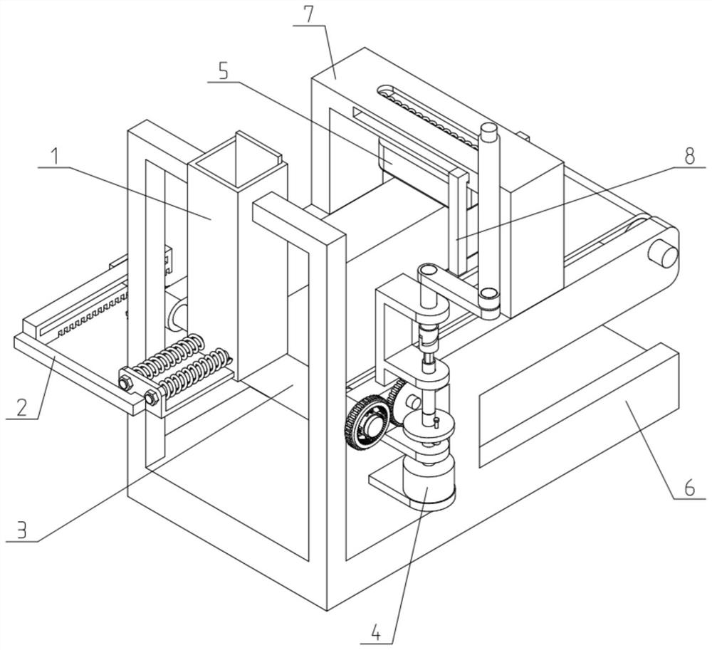
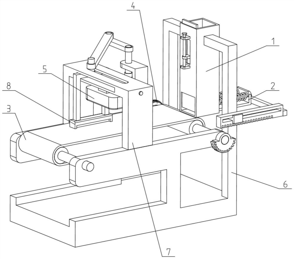
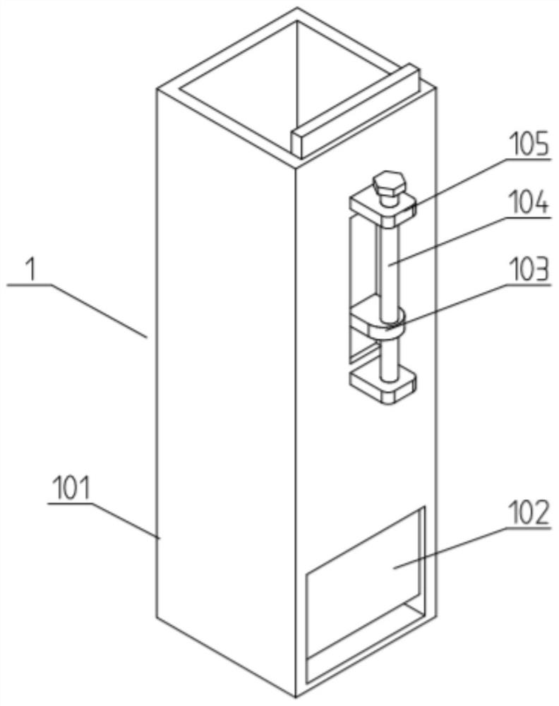
[0040] Such as Figure 1-14 As shown, the intelligent digital chip factory inspection device includes a chip box 1, a chip ejection unit 2, a chip conveyor belt 3, a drive unit 4, a chip detector 5, a frame 6 and a door-shaped stand 7, and the chip box 1 fixedly connected to the frame 6; the chip box 1 is connected to the chip ejection unit 2; the chip ejection unit 2 is slidably fitted in the chip outlet at the front end of the chip box 1; The two ends of the conveyor belt 3 are movably connected to the front and rear ends of the frame 6; the chip conveyor belt 3 is connected to the chip ejection unit 2 by transmission; the chip conveyor belt 3 is located at the front end of the chip outlet; The drive unit 4 is fixedly connected to the frame 6; the drive unit 4 is connected to the chip conveyor belt 3; the door-shaped stand 7 is fixedly connected to the frame 6; the door-shaped stand The middle of the frame 7 is fixedly connected with the chip detector 5; the chip detector 5...
specific Embodiment approach 2
[0043] Such as Figure 1-14 As shown, the chip conveyor belt 3 includes a rear conveyor roller 301, a conveyor belt 302, a front conveyor roller 303 and an incomplete gear 304; the front conveyor roller 303 and the rear conveyor roller 301 are connected by a transmission belt 302; The front conveying roller 303 and the rear conveying roller 301 are respectively rotatably connected to the front and rear ends of the frame 6; one end of the rear conveying roller 301 is connected to the drive unit 4 in transmission; the rear conveying roller 301 The other end is fixedly connected to the incomplete gear 304 ; the incomplete gear 304 is meshed and driven to connect with the chip ejection unit 2 . The rear conveying roller 301 inside the chip conveying belt 3 rotates under the drive of the driving unit 4, and the rear conveying roller 301 is connected to the front conveying roller 303 through the conveying belt 302, thereby driving the front conveying roller 303 Rotate, when the rea...
specific Embodiment approach 3
[0045] Such as Figure 1-14 As shown, the chip ejection unit 2 includes a linkage rack 201, a linkage rod 202, a push slide plate 203, a guide shaft 204, a reset compression spring 205, a spring seat plate 206 and a limit nut 207; the lower end of the linkage rack 201 The teeth of the gear are meshed with the incomplete gear 304 for transmission connection; the rear end of the linkage rack 201 is fixedly connected to one end of the linkage rod 202; the other end of the linkage rod 202 is fixedly connected to the spring seat plate 206; The lower end of the spring seat plate 206 is fixedly connected to the rear end of the push slide plate 203; the front end of the push slide plate 203 is slidably fitted in the chip outlet at the front end of the chip box 1; the spring seat plate 206 is slidably fitted in two The middle part of the guide shaft 204; the front ends of the two guide shafts 204 are fixedly connected to the chip box 1; the rear ends of the two guide shafts 204 are res...
PUM
 Abstract
Description
Claims
Application Information
 - R&D Engineer
- R&D Manager
- IP Professional
- Industry Leading Data Capabilities
- Powerful AI technology
- Patent DNA Extraction
Browse by: Latest US Patents, China's latest patents, Technical Efficacy Thesaurus, Application Domain, Technology Topic.
© 2024 PatSnap. All rights reserved.Legal|Privacy policy|Modern Slavery Act Transparency Statement|Sitemap