
Hydrocarbon source rock hydrocarbon generation potential prediction method

A technology of hydrocarbon generation potential and prediction method, which is applied in the field of geological research, can solve problems such as expensive testing costs, failure to meet the exploration needs of source rocks, and inability to accurately reflect the hydrocarbon generation potential of source rocks, and achieve the effect of reducing operating costs

Active Publication Date: 2020-09-04
PETROCHINA CO LTD
View PDF5 Cites 0 Cited by
  • Summary
  • Abstract
  • Description
  • Claims
  • Application Information

AI Technical Summary

Problems solved by technology

[0003] At present, the method for determining the hydrocarbon-generating potential of source rocks is mainly determined by laboratory organic geochemical analysis. Therefore, if the number of test samples is small, the hydrocarbon generation potential of the source rock cannot be accurately reflected; if a large number of test samples are used to statistically determine the hydrocarbon generation potential of the source rock, the test cost is very expensive
Therefore, determining the hydrocarbon-generating potential of source rocks by conventional organic geochemical methods cannot meet the exploration needs of low-exploration sags with few source rock samples.

Method used


Image

  • Hydrocarbon source rock hydrocarbon generation potential prediction method
  • Hydrocarbon source rock hydrocarbon generation potential prediction method
  • Hydrocarbon source rock hydrocarbon generation potential prediction method

Examples


Embodiment 1

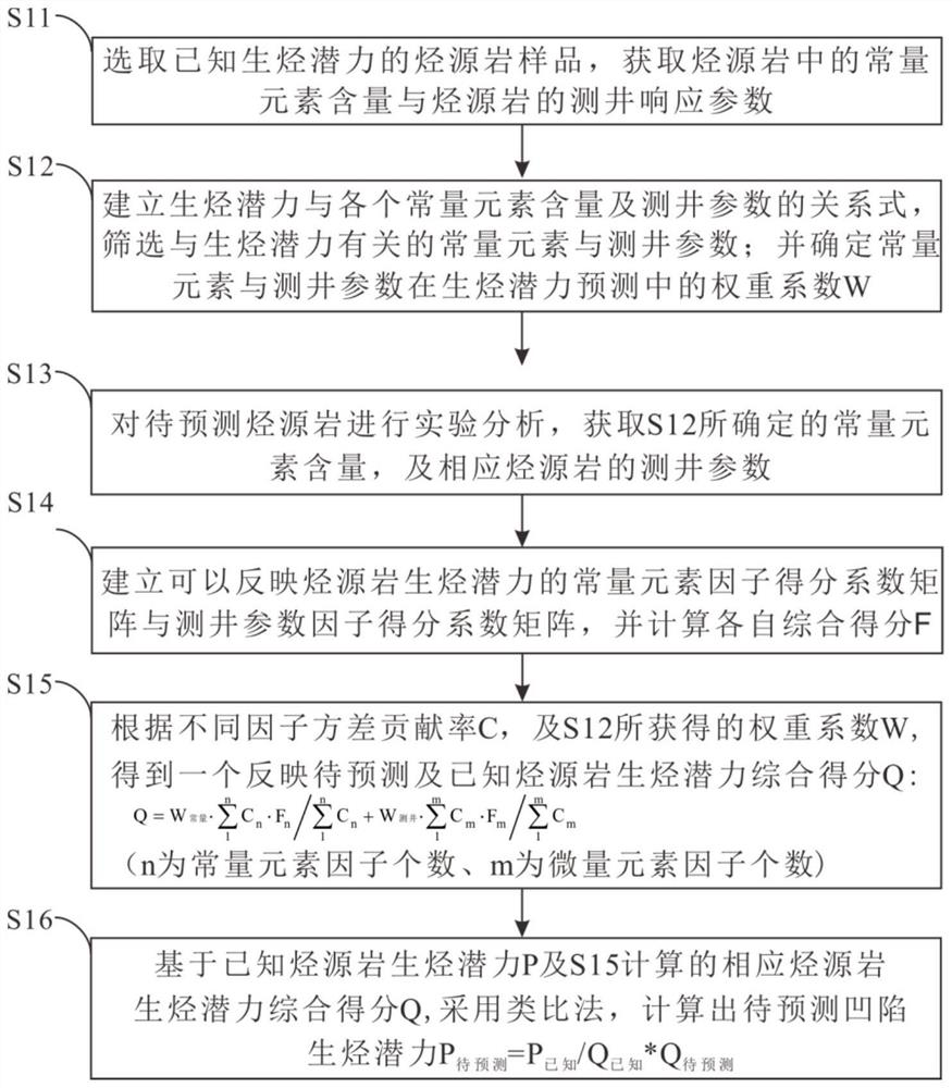
[0045] Such as figure 1The flowchart of implementation of the source rock hydrocarbon generation potential prediction method shown in this embodiment includes:

[0046] S11, obtain source rock samples A, B, C, and D with known hydrocarbon generation potential P of 19.53mg / g, 6.21mg / g, 12.64mg / g, and 25.12mg / g, and use titration method to obtain major elements in the laboratory content percentage, including 11 standard elements such as Ca, K, and Ti; the logging parameters are obtained from the logging curves of GR (natural gamma ray), DT (acoustic time difference), LLD (deep lateral resistivity), MSFL (micro Ball resistivity) LLS (shallow lateral resistivity), DEN (formation density), NPHI (neutron porosity), SP (natural gamma ray), U (radioactive U), CAL (well diameter), DIP (formation dip ) and other 11 kinds of source rock samples corresponding to the conventional logging data.

[0047] S12, take the hydrocarbon generation potential P of the four groups of data A, B, C, a...


PUM


Abstract

The invention provides a hydrocarbon source rock hydrocarbon generation potential prediction method. The method comprises the following steps: S11, selecting a hydrocarbon source rock sample with known hydrocarbon generation potential, and obtaining standard constant element content in hydrocarbon source rock and conventional logging response parameters of the hydrocarbon source rock; S12, establishing relational expressions between the hydrocarbon generation potential and the content of each constant element as well as the logging parameters, and screening the constant elements and the logging parameters related to the hydrocarbon generation potential; determining a weight coefficient W of the constant elements and the logging parameters in hydrocarbon generation potential prediction; S13, performing experimental analysis on the hydrocarbon source rock to be predicted to obtain the content of the constant elements determined in the S12 and the logging parameters of the corresponding hydrocarbon source rock; S14, establishing a constant element factor score coefficient matrix and a logging parameter factor score coefficient matrix which can reflect the hydrocarbon generation potential of the hydrocarbon source rock, and calculating respective comprehensive scores F; S15, calculating a comprehensive score Q reflecting the hydrocarbon generation potentials of the hydrocarbon source rock to be predicted and the known hydrocarbon source rock according to the weight coefficient W obtained in the step S12; and S16, calculating the hydrocarbon generation potential of the hydrocarbon source rock to be predicted.

Description

technical field [0001] The invention relates to the technical field of geological research, in particular to a method for predicting hydrocarbon-generating potential of source rocks. Background technique [0002] The determination of the hydrocarbon-generating potential of source rocks is directly related to drilling investment and drilling success rate. For sags that have not yet confirmed the hydrocarbon-generating potential of source rocks, whether the hydrocarbon-generating potential of source rocks in the sags can be accurately predicted is crucial to improving the benefits of oil and gas exploration. It is very important to say. [0003] At present, the method for determining the hydrocarbon-generating potential of source rocks is mainly determined by laboratory organic geochemical analysis. Therefore, if the number of test samples is small, the hydrocarbon generation potential of the source rock cannot be accurately reflected; if a large number of test samples are us...

Claims


Application Information

Patent Timeline
IPC IPC(8): G01V11/00G06Q10/04G06Q10/06G06Q50/02
CPCG01V11/00G06Q10/04G06Q10/0639G06Q50/02
Inventor 薛罗史忠生马轮陈彬滔王磊白洁史江龙
Owner PETROCHINA CO LTD
Learn More