
Opposite substrate

A technology for facing substrates and substrates, applied in the direction of instruments, electrical digital data processing, electrical components, etc., can solve the problems of mixed light, insufficient aperture ratio, and insufficient light-shielding ability, so as to avoid insufficient aperture ratio, improve light mixing, and optimize The effect of shading ability

Active Publication Date: 2020-09-04
AU OPTRONICS CORP
View PDF8 Cites 0 Cited by
  • Summary
  • Abstract
  • Description
  • Claims
  • Application Information

AI Technical Summary

Problems solved by technology

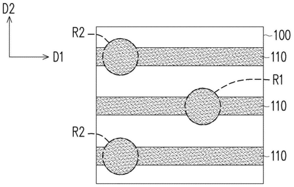
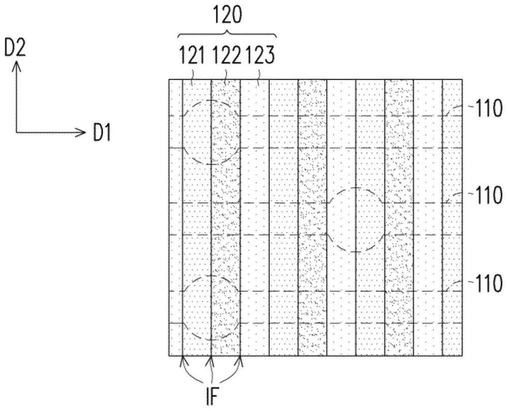
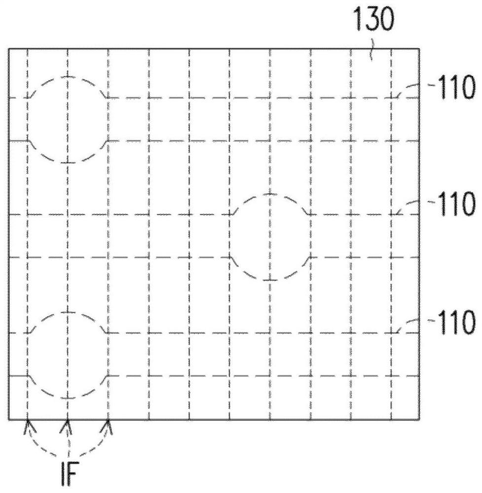
[0003] The present invention provides an opposite substrate, which can improve the problems of insufficient light-shielding ability, light mixing and insufficient aperture ratio, etc.

Method used


Image

  • Opposite substrate
  • Opposite substrate
  • Opposite substrate

Examples


Embodiment Construction

[0061] Reference will now be made in detail to the exemplary embodiments of the present invention, examples of which are illustrated in the accompanying drawings. Wherever possible, the same reference numbers will be used in the drawings and description to refer to the same or like parts.

[0062] The directional terms mentioned in the embodiments, such as "up", "down", "front", "rear", "left", "right", etc., are only referring to the directions of the drawings. Accordingly, the directional terms used are illustrative, not limiting, of the invention. In the drawings, each figure illustrates the general characteristics of methods, structures and / or materials used in particular embodiments. However, these figures should not be interpreted as defining or limiting the scope or nature encompassed by these embodiments. For example, the relative sizes, thicknesses and positions of layers, regions and / or structures may be reduced or exaggerated for clarity. It will be understood th...


PUM


Abstract

The invention discloses an opposite substrate which comprises a substrate body, a plurality of first shading patterns, a plurality of second shading patterns, a flat layer and a plurality of supporting pieces. The plurality of supporting pieces are located in a plurality of primary support regions and a plurality of secondary support regions of the opposing substrate. The plurality of first lightshielding patterns extend along a first direction, wherein the material of the plurality of first light shielding patterns comprises an organic material. The plurality of second light shielding patterns extend along the second direction, wherein the material of the plurality of second light shielding patterns comprises metal. The first shading patterns and the second shading patterns are located on the opposite sides of the flat layer respectively. Alternatively, the plurality of first light shielding patterns and the plurality of second light shielding patterns are located on the same side ofthe flat layer, and the flat layer has a plurality of openings overlapping the plurality of supporting pieces located in the plurality of secondary support regions, respectively.

Description

technical field [0001] The invention relates to a counter substrate, and in particular to a counter substrate suitable for a display. Background technique [0002] With the advancement of technology, the demand for displays with high resolution is getting higher and higher. Taking a Head Mounted Display (HMD) as an example, it utilizes a lens group to project a display image into human eyes, allowing the user to see a magnified virtual image. In order to achieve the immersion of Virtual Reality (VR) and enhance the detail of images, the resolution of the head-mounted display needs to be above 1000PPI (Pixel Per Inch). However, limited by the current manufacturing process technology, manufacturing process limits and material characteristics, the light-shielding pattern of the opposite substrate in the display may be poorly produced with the increase of resolution, resulting in insufficient light-shielding ability, light mixing and insufficient aperture ratio. And other issu...

Claims


Application Information

Patent Timeline
Patent Type & Authority Applications(China)
IPC IPC(8): G09F9/30G02F1/1335G02B27/01
CPCG09F9/30G02F1/133512G02B27/0172H10K59/8792G06F3/0412G06F3/0446G06F3/0445G02F1/133357G02F1/13394H10K59/38H10K59/40G02F1/13338G02F1/133514G02F1/136286G06F3/041G06F2203/04103G06F2203/04107
Inventor 吕思慧叶家宏黄国有
Owner AU OPTRONICS CORP
Learn More