Novel high-low voltage isolation switch

A high and low voltage isolation and switching technology, used in electrical switches, high-voltage air circuit breakers, air switch components, etc., can solve problems such as damage to electrical contacts, affecting line reliability, safe and stable operation of power supply grids, and contact separation.

Inactive Publication Date: 2020-09-04
温州市鹿城区渊龙电器科技有限公司
View PDF0 Cites 2 Cited by
  • Summary
  • Abstract
  • Description
  • Claims
  • Application Information

AI Technical Summary

Problems solved by technology

Because most of the high-voltage isolation switches are outdoors, the operating conditions are harsh, and most of the components are basically exposed. Due to the long-term impact of the external environment and climate, the electrical contacts of the isolation switch are oxidized to varying degrees, and the contact surface turns black.
Frequent operation of the isolating switch, serious damage to the electrical contacts, corrosion, cracks, and peeling off of the coating, etc., resulting in excessive contact resistance and high temperature rise of the electrical contacts, affecting the working performance of the isolating switch, which in turn affects the reliability of the entire circuit Safe and stable operation of permanent power supply and power grid
[0003] However, in the actual use of the prior art, the switch knife is not firmly fixed, and maintenance personnel can easily touch the switch knife by mistake. detachment, thereby creating a hazard to maintenance personnel and appliances

Method used


Image

  • Novel high-low voltage isolation switch
  • Novel high-low voltage isolation switch
  • Novel high-low voltage isolation switch

Examples


Embodiment Construction

[0025] The technical solutions in the embodiments of the present invention will be clearly and completely described below in conjunction with the accompanying drawings in the embodiments of the present invention. Obviously, the described embodiments are only a part of the embodiments of the present invention, rather than all the embodiments. Based on the embodiments of the present invention, all other embodiments obtained by those of ordinary skill in the art without creative work shall fall within the protection scope of the present invention.

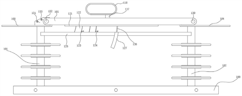
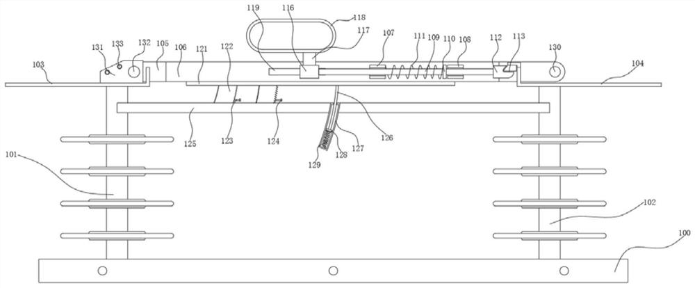
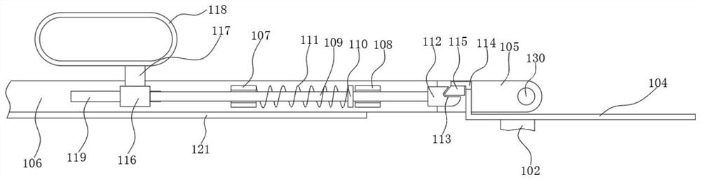
[0026] See Figure 1-5 , The present invention provides a technical solution: including a support base 100, the top of the support base 100 is respectively fixedly installed with a left insulation pillar 101 and a right insulation pillar 102, the top of the left insulation pillar 101 is fixedly installed with a left wiring contact 103, and the right insulation The top of the pillar 102 is fixedly installed with a right wiring contact 104...


PUM


Abstract

The invention discloses a novel high-low voltage isolation switch. The isolation switch comprises a supporting seat, the top of the supporting seat is fixedly connected with a left insulating supporting column and a right insulating supporting column. The top of the left insulating supporting column is fixedly connected with a left wiring contact. A left wiring contact is fixedly connected to thetop of the left insulating supporting column, a right wiring contact is fixedly connected to the top of the right insulating supporting column, a disconnecting link is movably arranged at the top of the left wiring contact and the top of the right wiring contact, insulating partition plates are fixedly connected to the inner wall of the disconnecting link, and a first guide pipe and a second guidepipe are fixedly connected between the two insulating partition plates. According to the invention, the disconnecting link is rotated, so that the disconnecting link drives a movable rod to rotate through the insulating partition plates, the first guide pipe and the second guide pipe; and the movable rod drives the clamping head to rotate, and the surface of the clamping block is clamped with theinner wall of the clamping groove, so that the disconnecting link can be prevented from rotating reversely by matching the clamping block with the clamping head and the clamping groove, and the disconnecting link is firmly arranged at the top of the left wiring contact and the top of the right wiring contact.

Description

Technical field [0001] The invention relates to the technical field of isolation switches, in particular to a new type of high and low voltage isolation switches. Background technique [0002] The high-voltage isolating switch is the key equipment in the power system. It mainly isolates the overhauled high-voltage bus, circuit breaker and other electrical equipment from the live high-voltage line, and switches the high-voltage line under no-load conditions according to the operation requirements of the power grid. Load current, etc., is one of the most widely used high-voltage switchgear in the power system. Because the high-voltage isolation switches are mostly outdoors and the operating conditions are harsh, most of the components are basically exposed, and they are affected by the external environment and climate for a long time. The electrical contacts of the isolation switches are oxidized to varying degrees and the surface of the contacts becomes black. The isolation switc...

Claims


Application Information

Patent Timeline
IPC IPC(8): H01H31/02H01H3/60
CPCH01H3/60H01H31/02H01H31/026
Inventor 余成鹏
Owner 温州市鹿城区渊龙电器科技有限公司
Why Eureka
Try Eureka