A filter power splitter

A power divider and resonator technology, which is applied to waveguide-type devices, circuits, connecting devices, etc., can solve the problem that the power divider cannot have passband selectivity, achieve good passband selectivity, and suppress high-order harmonics. , the effect of extending the stopband bandwidth

Active Publication Date: 2021-09-24
ZHONGTIAN BROADBAND TECH +1
View PDF5 Cites 0 Cited by
  • Summary
  • Abstract
  • Description
  • Claims
  • Application Information

AI Technical Summary

Problems solved by technology

[0003] The main purpose of the present invention is to propose a filter power splitter, which aims to solve the technical problem that the existing power splitter cannot have better passband selectivity

Method used


Image

  • A filter power splitter
  • A filter power splitter
  • A filter power splitter

Examples


Embodiment Construction

[0038] The following will clearly and completely describe the technical solutions in the embodiments of the present invention with reference to the accompanying drawings in the embodiments of the present invention. Obviously, the described embodiments are only part of the embodiments of the present invention, not all of them. Based on the embodiments of the present invention, all other embodiments obtained by persons of ordinary skill in the art without creative efforts fall within the protection scope of the present invention.

[0039] It should be noted that if there is a directional indication (such as up, down, left, right, front, back...) in the embodiment of the present invention, the directional indication is only used to explain the position in a certain posture (as shown in the accompanying drawing). If the specific posture changes, the directional indication will also change accordingly.

[0040] In addition, if there are descriptions involving "first", "second" and ...


PUM


Abstract

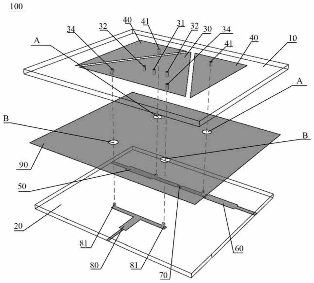
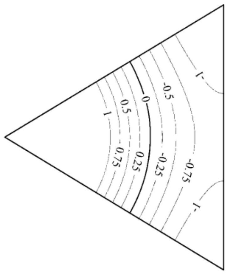
The invention discloses a filter power divider. In the technical solution of the present invention, a ground plate is provided between the first substrate and the second substrate, the ground plate is a metal plate, and a first resonator and two second resonators are provided on the surface of the first substrate away from the second substrate, The two second resonators are spaced apart from the first resonator to form a coupling effect. The equivalent common-mode signal excited by the two open-circuit ends of the T-shaped feeder at the bottom of the second substrate is fed into the first resonator through the metal via. When the first resonator works at TM 10 In the mode, the resonance mode generated by the differential excitation on the first resonator can be suppressed. On this basis, along the first resonator TM 10 The middle point of the mode zero potential distribution line is symmetrically introduced into the metal through hole electrically connected to the ground plane of the middle layer, thereby further suppressing high-order harmonics, and providing an additional transmission zero point, so that the filter power splitter of the present invention has better The passband selectivity expands the stopband bandwidth of the filter power splitter of the present invention.

Description

technical field [0001] The invention relates to the technical field of filters, in particular to a filter power divider. Background technique [0002] Power dividers and filters are important passive components for power distribution / combining and signal selection in microwave and millimeter wave systems, respectively. In existing power splitters, the harmonics at the high end of the passband are still very close to the operating frequency, and better passband selectivity cannot be obtained. Contents of the invention [0003] The main purpose of the present invention is to propose a filter power splitter, aiming at solving the technical problem that the existing power splitter cannot have better passband selectivity. [0004] In order to achieve the above object, a filter power splitter proposed by the present invention, the filter power splitter includes: [0005] a first substrate and a second substrate stacked on top of each other; [0006] a ground plate, the ground...

Claims


Application Information

Patent Timeline
Patent Type & Authority Patents(China)
IPC IPC(8): H01P1/213H01P1/212H01P5/16
CPCH01P1/212H01P1/2135H01P5/16
Inventor 王建朋顾辉葛磊
Owner ZHONGTIAN BROADBAND TECH
Why Eureka
Try Eureka