
A Reflectionless Bandpass Filter Based on Double-Sided Parallel Striplines

A double-sided parallel stripline and bandstop filter technology, which is applied to waveguide devices, circuits, electrical components, etc., can solve problems such as high insertion loss, limitation, and widening of microstrip line width, and achieve high characteristic impedance values , the effect of wide relative absorption bandwidth and narrow 1dB relative bandwidth

Active Publication Date: 2021-10-29
NANTONG UNIVERSITY
View PDF9 Cites 0 Cited by
  • Summary
  • Abstract
  • Description
  • Claims
  • Application Information

AI Technical Summary

Problems solved by technology

However, at the same time, the width of the microstrip line with lower characteristic impedance becomes wider, and the appearance of lateral high-order modes limits its operation at high frequencies.
In previous designs, coupled microstrips are usually used to achieve high equivalent impedance, but it will inevitably lead to higher insertion loss

Method used


Image

  • A Reflectionless Bandpass Filter Based on Double-Sided Parallel Striplines
  • A Reflectionless Bandpass Filter Based on Double-Sided Parallel Striplines
  • A Reflectionless Bandpass Filter Based on Double-Sided Parallel Striplines

Examples


Embodiment Construction

[0027] The present invention will be further described below in conjunction with the accompanying drawings and specific embodiments.

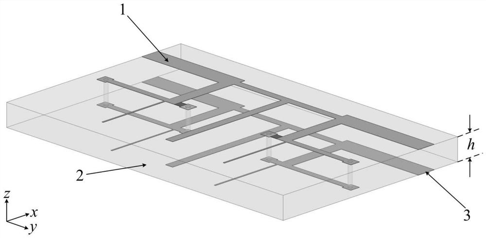
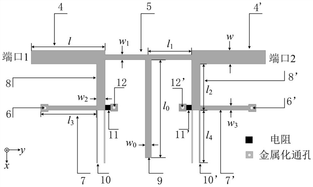
[0028] see figure 1 and figure 2 They are respectively the 3D perspective view and the top view of the non-reflection bandpass filter based on double-sided parallel strip lines implemented by the present invention. The filter implemented by the present invention includes an upper layer metal strip 1, a substrate 2 and a lower layer metal strip 3 which are stacked sequentially from top to bottom. The upper metal strip 1 and the lower metal strip 2 both include a 50Ω transmission line 4 at the input end, a 50Ω transmission line 4' at the output end, a T-shaped bandpass filter arranged between the input and output transmission lines, and two connected to the input and output transmission lines. Absorptive band-stop filters arranged symmetrically.

[0029]Wherein, the T-shaped bandpass filter is composed of a half-wavelength transmission line 5...


PUM

PropertyMeasurementUnit
thicknessaaaaaaaaaa

Abstract

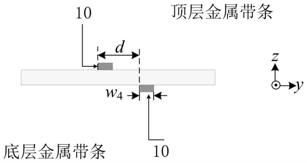
The invention relates to a non-reflection band-pass filter based on double-sided parallel strip lines, which includes a substrate, an upper metal strip and a lower metal strip that are parallel to each other and are metal grounded on the upper bottom surface and the lower bottom surface of the substrate. Both upper and lower metal strips contain a T-shaped bandpass filter and two symmetrically arranged absorption bandstop filters. An offset of distance d is formed between the quarter-wavelength open-circuit stubs of the absorption band-stop filters of the upper and lower metal strips. By offsetting the upper and lower layers of parallel striplines (a quarter-wavelength open-circuit stub), a high characteristic impedance value of more than 300Ω is easily obtained, which makes the proposed filter break through the process limit and can achieve high impedance values. And it has narrow 1dB relative bandwidth, wide 20dB relative absorption bandwidth and good passband selectivity. The band-pass filter part of the T-shaped structure introduces a half-wavelength open-circuit stub to generate two transmission zero points, which significantly enhances the selectivity.

Description

technical field [0001] The invention relates to the technical field of wireless communication, in particular to a non-reflection bandpass filter based on double-sided parallel striplines. Background technique [0002] Filters are an essential part of RF and microwave systems to mitigate interfering signals and unwanted spectral generation outside the system. Among them, the band-pass filter is a key frequency-selective component and plays a vital role in microwave / RF systems. Traditional filters reflect the energy of out-of-band signals back to the signal source, usually such reflections degrade the performance of adjacent active devices, causing unavoidable interference. For this reason, additional components such as attenuators are often used to improve performance, but this also leads to problems such as reduced dynamic range and increased circuit size. With the continuous development of 5G communication, the requirements for radio frequency circuits have also become hi...

Claims


Application Information

Patent Timeline
Patent Type & Authority Patents(China)
IPC IPC(8): H01P1/20
CPCH01P1/20
Inventor 陈建新朱雅慧蔡璟
Owner NANTONG UNIVERSITY
Learn More