Power battery cell positioning clamp

A technology for positioning fixtures and power batteries, applied in the field of positioning fixtures for power battery cells, can solve the problems of high cost and large space occupied by the positioning fixtures, and achieve the effect of low cost and small space occupation

Active Publication Date: 2020-09-08
深圳市大族锂电智能装备有限公司
View PDF5 Cites 2 Cited by
  • Summary
  • Abstract
  • Description
  • Claims
  • Application Information

AI Technical Summary

Problems solved by technology

[0002] The battery cell is a part of the power battery. In the production process of the power battery, the battery cell needs to be positioned at many stations. In the process of positioning, the long side and the short side of the battery cell shape are generally positioned. The long side and short side of the core are positioned. The positioning fixture used in the related art is generally equipped with multiple sets of cylinders for positioning and clamping the different positions of the battery cell, so that the overall space occupied by the positioning fixture is larger and the cost is higher.

Method used


Image

  • Power battery cell positioning clamp
  • Power battery cell positioning clamp
  • Power battery cell positioning clamp

Examples


Embodiment

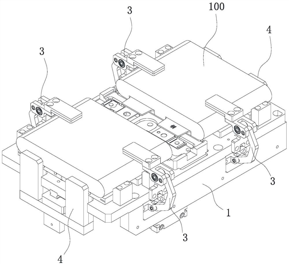
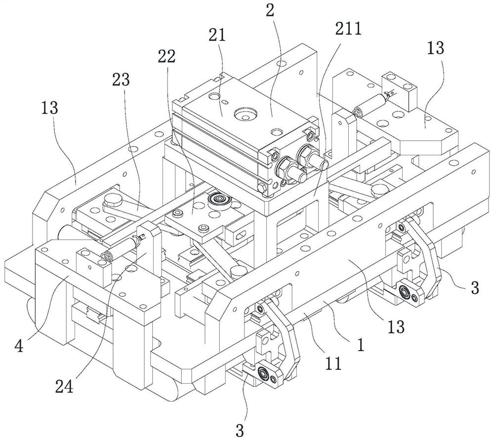
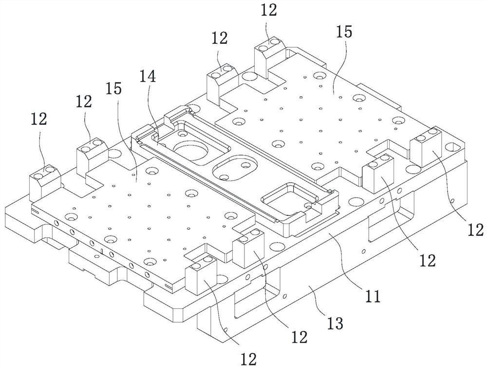
[0028] In this embodiment, as Figure 1-9As shown, the positioning fixture of the power battery cell includes: a mounting mechanism 1, a driving mechanism 2, a clamping mechanism 3 and a side positioning mechanism 4. The mounting mechanism 1 includes a bottom plate 11 and a limit block 12. The bottom plate 11 has a positioning surface, and the positioning surface There are two first sides parallel and opposite to each other, the positioning surface has two second sides connected between the two first sides, the first side of the bottom plate 11 is fixed with a limit block 12, and the driving mechanism 2 is arranged on The base plate 11, the clamping mechanism 3 is arranged at the two first sides of the base plate 11 and connected with the drive mechanism 2, the side positioning mechanism 4 is arranged at the two second sides of the base plate 11 and connected with the drive mechanism 2, the drive mechanism 2 It can drive the clamping mechanism 3 to perform a clamping action to...


PUM


Abstract

The invention provides a power battery cell positioning clamp. The power battery cell positioning clamp comprises a mounting mechanism, a driving mechanism, clamping mechanisms and side positioning mechanisms, wherein the mounting mechanism comprises a bottom plate and a limiting block, the bottom plate is provided with a positioning surface, the positioning surface is provided with two first sideedges, the positioning surface is provided with two second side edges connected between the two first side edges, limiting blocks are fixed to the first side edges of the bottom plate, the driving mechanism is arranged on the bottom plate, the clamping mechanisms are arranged on the two first side edges of the bottom plate and connected with the driving mechanism, the side positioning mechanismsare arranged on the two second side edges of the bottom plate and connected with the driving mechanism, the driving mechanism can drive the clamping mechanisms to do clamping actions towards the positioning surface and drive the side positioning mechanisms to move in the direction inside the positioning surface at the same time, and the driving mechanism can drive the clamping mechanisms to do loosening actions away from the positioning surface and drive the side positioning mechanisms to move in the direction outside the positioning surface at the same time. According to the scheme, the positioning clamp can position and clamp battery cells, and is small in occupied space and low in cost.

Description

technical field [0001] The invention belongs to the technical field of battery clamps, and in particular relates to a positioning clamp for power battery cells. Background technique [0002] The battery cell is a part of the power battery. During the production process of the power battery, the battery cell needs to be positioned at many stations. During the positioning process, the long and short sides of the battery cell shape are generally positioned. The long and short sides of the core are positioned. The positioning fixture used in the related art is generally equipped with multiple sets of cylinders for positioning and clamping different positions of the battery cell, which makes the overall occupied space of the positioning fixture larger and the cost is higher. . SUMMARY OF THE INVENTION [0003] The technical problem to be solved by the present invention is to provide a positioning fixture for a power battery cell, which can realize the positioning and clamping ...

Claims


Application Information

Patent Timeline
Patent Type & Authority Applications(China)
IPC IPC(8): B25B11/00H01M6/00H01M10/04
CPCB25B11/00H01M6/005H01M10/0404Y02P70/50
Inventor 于秀东刘兰王乾王文英农利锦肖曲高云松黄祥虎高云峰
Owner 深圳市大族锂电智能装备有限公司
Why Eureka
Try Eureka