Compass double-leg distance locking method

A compass foot and compass technology, applied in the field of stationery, can solve the problems of changes, the feet of the compass are not easily broken apart, and the operation is inconvenient.

Inactive Publication Date: 2020-09-08
QUANZHOU WENBAO LIGHT IND CO LTD
View PDF7 Cites 0 Cited by
  • Summary
  • Abstract
  • Description
  • Claims
  • Application Information

AI Technical Summary

Problems solved by technology

[0002] When using a compass, you need to separate the two legs of the compass to the required distance. The above-mentioned distance refers to the distance between the free ends of the two compass legs, and then pinch the head of the compass to draw a circle. The angle between the two feet may change, and the change of the angle will cause the distance between the two compass feet to change, resulting in the failure of drawing a circle. In order to overcome the above technical problems, direct control of the compass feet is usually used in the prior art The most common way to maintain the distance between the feet of the com...

Method used


Image

  • Compass double-leg distance locking method
  • Compass double-leg distance locking method
  • Compass double-leg distance locking method

Examples


Embodiment approach 1

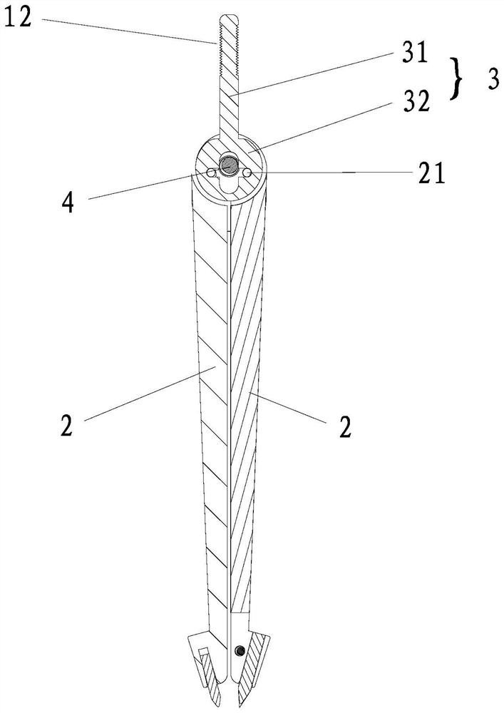
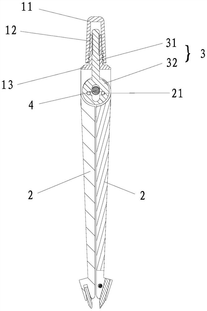
[0031] A method for locking the distance between the feet of a compass, comprising the steps of:

[0032] Step 1. Linearly slide and connect a handle in the compass head of the compass, and connect the handle with the two compass feet of the compass through a mechanism transmission, so that when the distance between the two compass feet changes The handle slides within the compass head.

[0033] Step 2: After adjusting the included angle between the two compass feet to a desired angle, fix the handle and the compass head together, and keep the handle and the compass head relative to each other.

[0034] Further, the compass head has a clamping device, and in the second step, the clamping device clamps the handle so as to keep the handle and the compass head relative to each other.

[0035] The above-mentioned mechanism can adopt the crank-slider mechanism and can also adopt the center piece mechanism adopted by the existing partial compasses. Specifically, in this embodiment,...

Embodiment approach 2

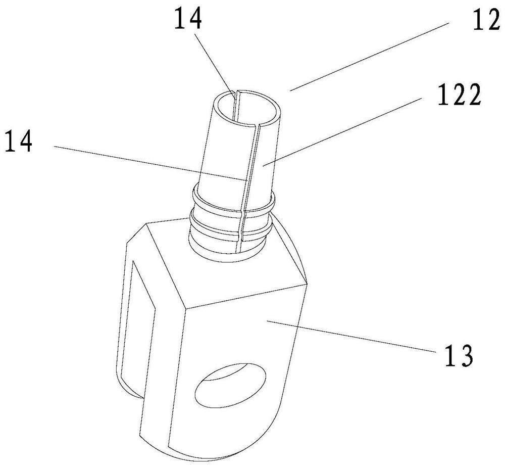
[0055] The difference between this embodiment and Embodiment 1 is that in this embodiment, the handle and the compass head are not fixed together by clamping the handle, but by clamping the handle from one side in the width direction of the handle Or place the handle on the compass head on one side in the thickness direction so as to keep the handle and the compass head relative to each other.

[0056] Specifically, in this embodiment, a locking device can be used to realize that the handle is on the compass head so as to keep the handle and the compass head relative to each other.

[0057] Such as Figure 12 As shown, the locking device includes a locking bolt 6 and a locking threaded hole 116 provided on the compass head. The compass head only includes the compass cap 11 and the compass head main body 13 connected together. The compass cap 116 is a cylinder Body, the locking threaded hole 116 runs through the compass cap 11 in the radial direction, the locking bolt 6 cooper...


PUM


Abstract

The invention discloses a compass double-leg distance locking method. The method comprises the following steps that 1, a handle is linearly slidably connected in a compass head of a compass, the handle is in transmission connection with two compass legs of the compass through a mechanism, and therefore the handle slides in the compass head when the size of the included angle of the two compass legs changes; 2, the handle and the compass head are fixed together when the included angle between the two compass legs is adjusted to a required angle, and the handle and the compass head are kept fixed relatively. By using the method, the pretightening force of the compass head can be reduced, when the compass is opened and closed, the two compass legs are easy to break off, more labor is saved during use, when the distance between the compass legs is adjusted, the handle is not limited, the compass legs can be quickly opened and closed, the handle and the compass head are fixed again when thedistance between the compass legs is locked, and use is more convenient.

Description

technical field [0001] The invention relates to the field of stationery, in particular to a method for locking the distance between the feet of a compass. Background technique [0002] When using a compass, you need to separate the two legs of the compass to the required distance. The above-mentioned distance refers to the distance between the free ends of the two compass legs, and then pinch the head of the compass to draw a circle. The angle between the two feet may change, and the change of the angle will cause the distance between the two compass feet to change, resulting in the failure of drawing a circle. In order to overcome the above technical problems, direct control of the compass feet is usually used in the prior art The most common way to maintain the distance between the feet of the compasses is to increase the pre-tightening force of the compasses head or to open threaded holes on the two feet of the compasses, and to add additional restrictions such as screws ...

Claims


Application Information

Patent Timeline
IPC IPC(8): B43L9/20B43L9/22
CPCB43L9/20B43L9/22
Inventor 黄丽
Owner QUANZHOU WENBAO LIGHT IND CO LTD
Why Eureka
Try Eureka