Transmission clamping device and automatic equipment

A technology of clamping device and transmission belt, which is applied in the directions of mechanical equipment, transportation and packaging, vibration suppression adjustment, etc., and can solve problems such as partial bending of products and blockage in the transmission process

Pending Publication Date: 2020-09-08
SUZHOU XUANKAI INTELLIGENT TECH CO LTD
View PDF5 Cites 1 Cited by
  • Summary
  • Abstract
  • Description
  • Claims
  • Application Information

AI Technical Summary

Problems solved by technology

[0004] The purpose of the present invention is to provide a transmission clamping device and automation equipment to solve the problem that the existing transmission rollers are easy to cause partial bending of the product after transmission on the basis of clamping, resulting in blockage in the subsequent transmission process

Method used


Image

  • Transmission clamping device and automatic equipment
  • Transmission clamping device and automatic equipment
  • Transmission clamping device and automatic equipment

Examples


Embodiment Construction

[0034] The purpose of the present invention is to provide a transmission clamping device and automation equipment to solve the problem that the existing transmission rollers are easy to cause partial bending of the product after transmission on the basis of clamping, resulting in blockage in the subsequent transmission process . In order to achieve the above purpose, the following technical solutions are specifically provided:

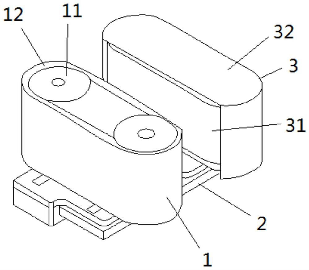
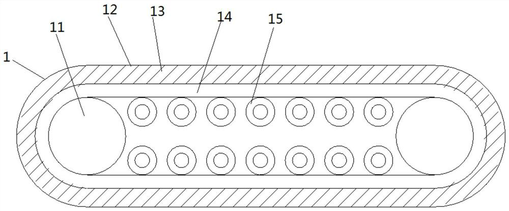
[0035] In the embodiment of the present invention, such as figure 1 , 3 As shown in -5, a transmission clamping device includes a moving extrusion belt structure 1 and a positioning extrusion belt structure 3;

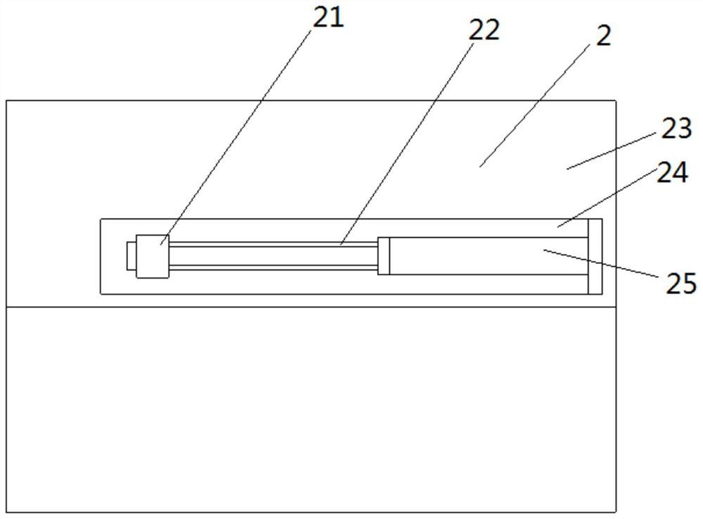
[0036] The device also includes a supporting plate structure 2;

[0037] The moving extrusion transmission belt structure 1 and the positioning extrusion transmission belt structure 3 are distributed in parallel on the pallet structure 2, while the mobile extrusion transmission belt structure 1 is slidably connected to the pallet structure 2...


PUM


Abstract

The invention is applicable to the field of automatic equipment, and particularly relates to a transmission clamping device and automatic equipment. The transmission clamping device comprises a movable extrusion transmission belt structure, a positioning extrusion transmission belt structure and a supporting plate structure, wherein the movable extrusion transmission belt structure is slidably connected to the supporting plate structure, and an automatic moving structure is used for closing the movable extrusion transmission belt structure and the positioning extrusion transmission belt structure for clamping transmission; the movable extrusion transmission belt structure comprises a transmission belt body used for transmission, the outer layer of the transmission belt body is sleeved withan outer belt, and a plurality of unit movable belts and a plurality of elastic filling strips which are distributed in a crossed array mode are arranged on the outer belt; the movable extrusion transmission belt structure and the positioning extrusion transmission belt structure get close for clamping transmission; and in cooperation with the plurality of unit movable belts and the plurality ofelastic filling strips which are arranged on the outer belt and distributed in a crossed array mode, the stability of transmission friction force is improved on the basis that the transmission area isincreased, and the problem of blockage in the transmission process is solved.

Description

technical field [0001] The invention belongs to the field of automation equipment, in particular to a transmission clamping device and automation equipment. Background technique [0002] Transmission refers to the power transmission between machines, and it can also be said that the mechanical power is transmitted to the terminal equipment through an intermediate medium. At present, the transmission mechanism used in the field of automation equipment mostly uses multiple sets of transmission rollers for clamping and transmission in order to be able to clamp and ensure that the integrity of the overall structure of the product is not damaged. [0003] The existing drive roller is easy to cause local bending of the product after transmission on the basis of ensuring clamping, causing blockage in the subsequent transmission process. Contents of the invention [0004] The purpose of the present invention is to provide a transmission clamping device and automation equipment to...

Claims


Application Information

Patent Timeline
Patent Type & Authority Applications(China)
IPC IPC(8): B65G15/30B65G15/14F16F15/067
CPCB65G15/14B65G15/30F16F15/067
Inventor 张靖
Owner SUZHOU XUANKAI INTELLIGENT TECH CO LTD
Why Eureka
Try Eureka