
Pile foundation conversion method and structure for bridge

A conversion method and technology for converting structures, which are applied in infrastructure engineering, bridges, bridge parts, etc., can solve the problems of insufficient bearing capacity, adverse effects of subway structures, large overall settlement, etc., to improve stability, avoid adverse effects, and solve problems. The effect of insufficient carrying capacity

Pending Publication Date: 2020-09-08
CHINA RAILWAY FIFTH SURVEY & DESIGN INST GRP
View PDF0 Cites 3 Cited by
  • Summary
  • Abstract
  • Description
  • Claims
  • Application Information

AI Technical Summary

Problems solved by technology

[0003] The existing technology only uses temporary support for the upper structure of the affected bridge piles for temporary roofing, and the upper load is transferred to the ground. A new foundation has not been constructed. After the subway section is crossed, the temporary roofing structure is removed, and the remaining piles If the foundation continues to be used, the pile foundation will transfer the concentrated load to the subway section structure, which will have an adverse impact on the subway structure, and the remaining pile foundation of the bridge may have insufficient bearing capacity, resulting in excessive overall settlement and seriously affecting the use of the bridge. Municipal facilities pose serious safety hazards

Method used


Image

  • Pile foundation conversion method and structure for bridge
  • Pile foundation conversion method and structure for bridge
  • Pile foundation conversion method and structure for bridge

Examples


Embodiment 1

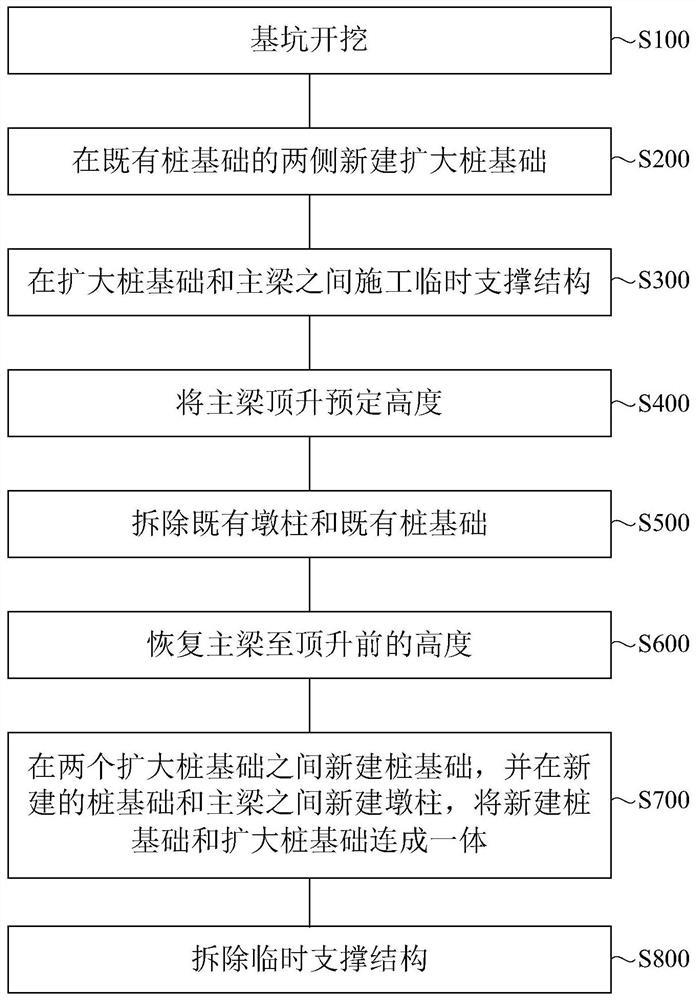
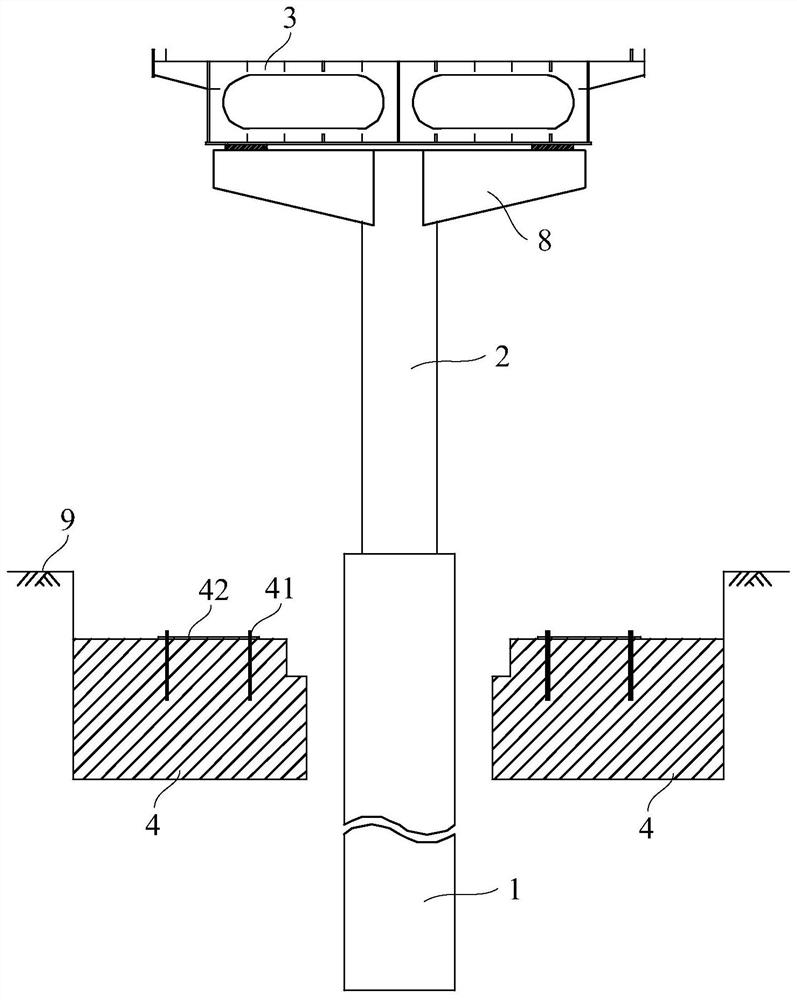
[0053] Such as figure 1 and Figure 6 As shown, the embodiment of the present application provides a bridge pile foundation conversion method, such as figure 2As shown in the structure, the bridge includes pile foundations, pier columns and main beams 3, and the pile foundation conversion method includes the following steps:

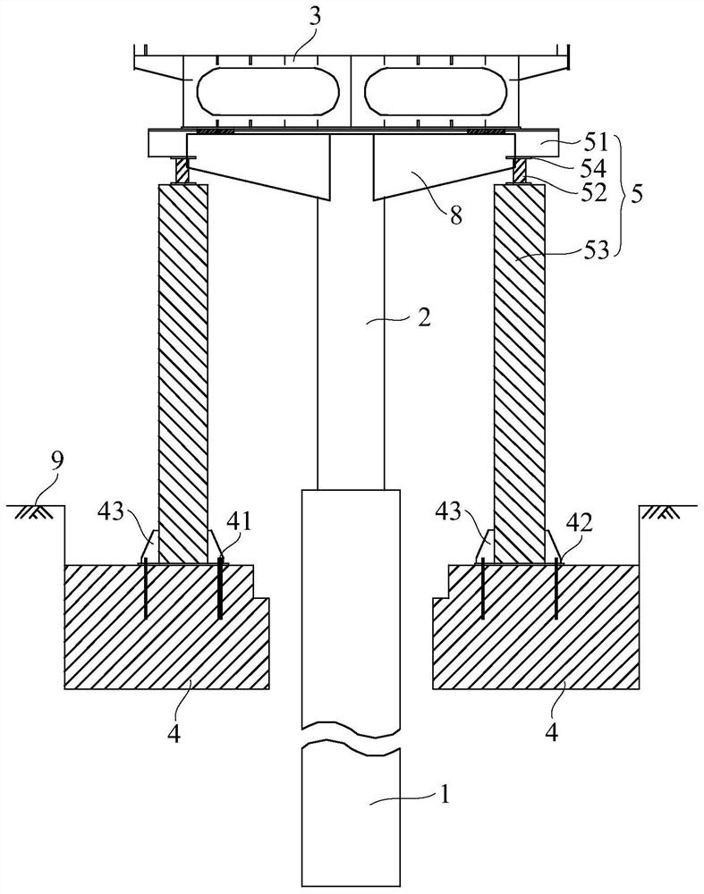
[0054] Step S200, building an expanded pile foundation 4 on both sides of the existing pile foundation 1, and the two expanded pile foundations 4 are arranged along the width direction of the bridge; figure 2 As shown in the structure, an enlarged pile foundation 4 is newly built on both sides of the existing pile foundation 1, and the arrangement direction of the two enlarged pile foundations 4 coincides with the width direction of the bridge, so as to be able to support the full width of the main beam 3; In order to facilitate the newly-built expanded pile foundation 4, such as figure 1 As shown, before the step S200 of building an expanded pile f...

Embodiment 2

[0064] The embodiment of the present application also provides a pile foundation conversion structure used in the above pile foundation conversion method, such as Figure 5 As shown in the structure, the pile foundation conversion structure is used for the pile foundation conversion of bridges, including: new pile foundation 6, expanded pile foundation 4, new pier column 7, temporary support structure 5 and beam 8; along the width direction of the bridge, in the new pile foundation An enlarged pile foundation 4 is respectively arranged on both sides of the foundation 6, and the newly-built pile foundation 6 and the enlarged pile foundation 4 are connected as a whole; the two enlarged pile foundations 4 are symmetrically arranged around the newly-built pile foundation 6; as Figure 6 As shown in the structure, the newly-built pile foundation 6 in the middle and the expanded pile foundation 4 on both sides are connected together to form a pile foundation after structural conversi...


PUM


Abstract

The invention relates to the technical field of constructional engineering, in particular to a pile foundation conversion method and structure for a bridge. The pile foundation conversion method comprises the steps that expanded pile foundations are newly built on the two sides of an existing pile foundation, and the two expanded pile foundations are arranged in the width direction of the bridge;a temporary supporting structure is constructed between the expanded pile foundations and a main beam; an existing pier column and the existing pile foundation are dismantled; and a pile foundation isnewly built between the two expanded pile foundations, a pier column is newly built between the newly-built pile foundation and the main beam, and the newly-built pile foundation and the expanded pile foundations are connected into a whole. The pile foundation conversion method can be completed before subway crossing on site, has the advantages of being convenient to construct and easy to convert, can break the original pile foundation conflicting with a subway interval structure, avoids adverse effects on a subway structure, and meanwhile solves the problem that the existing bridge pile foundation is insufficient in bearing capacity.

Description

technical field [0001] The present application relates to the technical field of construction engineering, in particular to a pile foundation conversion method and structure of a bridge. Background technique [0002] In urban rail transit projects, subway sections are generally laid along municipal roads. During the period, they will pass through complex strata, encounter municipal pipelines and buildings (structures), and inevitably encounter municipal facilities such as pedestrian bridges and urban overpasses. The facilities basically use mechanical hole-forming piles as the foundation. The bottom of the pile foundation is often buried deep, and there are often conflicts between the bridge pile foundation and the subway section. It is necessary to properly handle the relationship between the bridge pile foundation and the subway section to ensure that the subway construction and operation For the safety of municipal facilities during the period, when it is impossible to av...

Claims


Application Information

Patent Timeline
Patent Type & Authority Applications(China)
IPC IPC(8): E02D27/12E01D22/00E01D19/02
CPCE02D27/12E01D22/00E01D19/02
Inventor 李长安国斌罗章波郎瑶刘雪斌黄新连高煌李平定刘力周丁恒
Owner CHINA RAILWAY FIFTH SURVEY & DESIGN INST GRP
Learn More