Multi-channel floor drain

A multi-channel, floor drain technology, applied in the field of sanitary ware, can solve the problems of slow drainage speed, small water output, failure, etc., and achieve the effect of reducing the possibility and smooth drainage

Pending Publication Date: 2020-09-08
YONGGAO CO LTD
View PDF1 Cites 7 Cited by
  • Summary
  • Abstract
  • Description
  • Claims
  • Application Information

AI Technical Summary

Problems solved by technology

Traditional floor drains are generally water-sealed, the drainage speed is slow, the water seal is shallow, and the water seal in the floor drain is easy to dry up and smell bad
[0003] Such as my country's patent (application number is 201020504176.8) proposes a kind of adjustable height floor drain, this floor drain comprises a bell body and a housing, there is a water outlet pipe in the housing, the nozzle of the water outlet pipe is higher than the bottom surface of the housing, and the bell body is covered in On the outlet pipe, the distance from the top of the outlet pipe to the bottom of the housing is the maximum height of the water seal of the floor drain body. The space between the inner wall of the bell housing and the outer wall of the outlet pipe is used to store the water seal, resulting in a small amount of water seal storage and easy water seal. dry up
Secondly, since the water outlet pipe is located at the bottom of the casing, and the bell body must be prevented between the water outlet pipe and the casing, the diameter of the water outlet pipe is limited and cannot be enlarged, resulting in the problem of small water output.
[0004] In addition, people's requirements for the quality of the living environment are improved. The bathroom will adopt dry separation, install a floor drain in the shower room, and install a floor drain near the toilet or near the basin. The frequency of wading in the floor drain near the toilet is not high. It is easier to dry out and fail

Method used


Image

  • Multi-channel floor drain
  • Multi-channel floor drain
  • Multi-channel floor drain

Examples


Embodiment 1

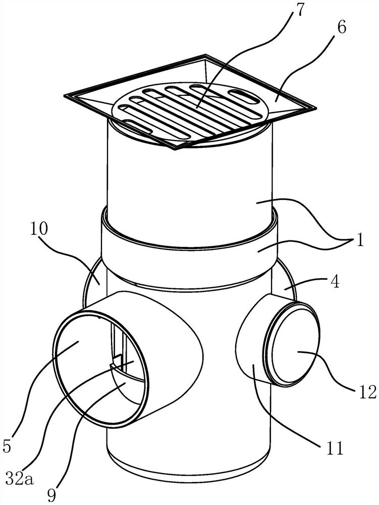
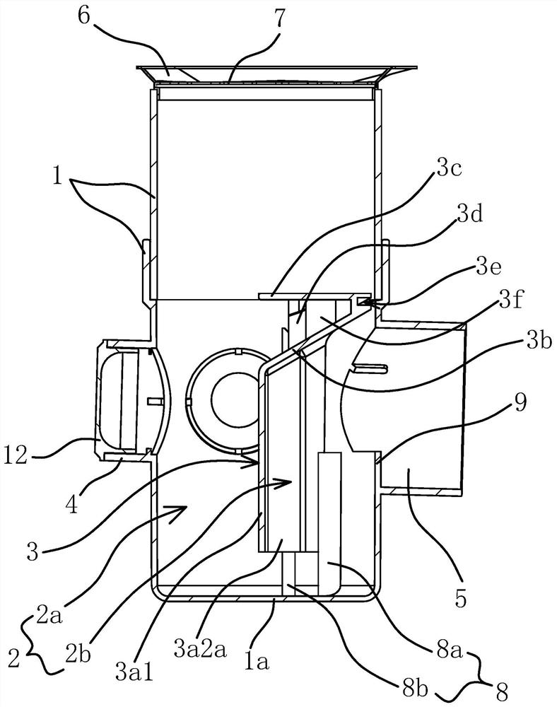
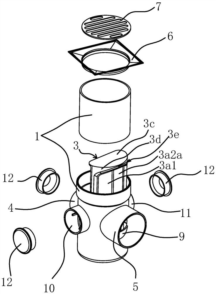
[0032] Such as Figure 1 to Figure 4As shown, the multi-channel floor drain includes a main pipe body 1 having a cavity 2, a diversion cover 6 and a floor drain cover 7 are provided on the top of the main pipe body 1, and a slot leading to the inside of the cavity 2 is provided on the floor drain cover 7, and the main pipe The bottom end of the body 1 is closed with a bottom plate 1a. The multi-channel floor drain is installed on the wading ground in the house, and the water flows into the cavity 2 from the floor drain cover 7 on the top of the main body 1. On the outer peripheral wall of the main body 1, there is also an outlet pipe 5 communicating with the cavity 2, and the water flows into the cavity 2. The water in the cavity 2 is discharged into the sewer from the outlet pipe 5. Since the outlet pipe 5 is located on the outer peripheral wall of the main body 1, the inner diameter of the outlet pipe 5 can be the same size as the inner diameter of the main body 1 to increas...

Embodiment 2

[0042] This embodiment is roughly the same as Embodiment 1, the difference is that three sets of limit assemblies 8 are provided on the inner wall of the main pipe body 1 to limit the rotation of the partition plate 3a in the main pipe body 1, and two sets of limit assemblies 8 are respectively located in the water outlet pipe. 5 on both sides, the limiting component 8 includes a limiting rib 1 8a and a limiting rib 2 8b arranged vertically. The third group of limiting components 8 is located above the water outlet pipe 5 , and the lower surface of the deflector 3 b is provided with inserting ribs inserted on the third group of limiting components 8 .

Embodiment 3

[0044] In this embodiment, it is roughly the same as the first embodiment, the difference is that both the partition plate 3 a and the deflector 3 b are integrally formed with the main pipe body 1 .


PUM


Abstract

The invention belongs to the technical field of bathrooms, and particularly relates to a multi-channel floor drain. The multi-channel floor drain solves the problems that an existing floor drain is insufficient in water outlet amount and low in water seal reliability. The multi-channel floor drain comprises a main pipe body with a containing cavity, and a flow guide cover and a floor drain cover are arranged at the top of the main pipe body; and the multi-channel floor drain is further characterized in that a bottom plate is arranged at the bottom end of the main pipe body in a closed mode, aseparator is arranged in the main pipe body and divides the containing cavity into a water inlet cavity and a water seal cavity, a channel for communicating the water inlet cavity with the water sealcavity is formed between the separator and the bottom plate, a first water inlet pipe communicating with the water inlet cavity and a water outlet pipe communicating with the water seal cavity are arranged on the peripheral wall of the main pipe body, the first water inlet pipe and the water outlet pipe are located above the channel and can form water seal between the water outlet pipe and the bottom plate, a guide plate positioned at the top of the water seal cavity is arranged on the separator, and the guide plate is obliquely arranged towards the water outlet pipe. According to the multi-channel floor drain, the water outlet amount of the floor drain and the reliability of water seal are improved.

Description

technical field [0001] The invention belongs to the technical field of sanitary ware, and in particular relates to a multi-channel floor drain. Background technique [0002] The floor drain is an important interface connecting the drainage pipe system and the indoor ground. As an important part of the drainage system in the residence, the performance of the floor drain directly affects the indoor air quality, which is very important for the control of the bathroom. Traditional floor drains are generally water-sealed, the drainage speed is slow, the water seal is shallow, and the water seal in the floor drain is easy to dry up and smell bad. [0003] Such as my country's patent (application number is 201020504176.8) proposes a kind of adjustable height floor drain, this floor drain comprises a bell body and a housing, there is a water outlet pipe in the housing, the nozzle of the water outlet pipe is higher than the bottom surface of the housing, and the bell body is covered ...

Claims


Application Information

Patent Timeline
Patent Type & Authority Applications(China)
IPC IPC(8): E03F5/04
CPCE03F5/0407Y02A30/60
Inventor 喻旭陈智勇孙华丽邓海亚
Owner YONGGAO CO LTD
Why Eureka
Try Eureka