Laser height pole device capable of controlling flatness of masonry

A technology of flatness and pictograph, which is applied in the field of laser pictograph devices, can solve the problems of affecting construction progress, construction inconvenience, and low construction efficiency, and achieve the effects of ensuring measurement accuracy, reducing measurement errors, and improving measurement accuracy

Inactive Publication Date: 2020-09-08
CHINA MCC17 GRP
View PDF6 Cites 1 Cited by
  • Summary
  • Abstract
  • Description
  • Claims
  • Application Information

AI Technical Summary

Problems solved by technology

[0003] The traditional number rod either moves while laying, or controls the two ends to build it with a line. The construction efficiency is low and the construction is inconvenient, especially in the case of a long wall. When the body wall is long, the line will be deflected, which will affect the accuracy of the masonry; and the line will be easily broken during the masonry process, which will affect the construction progress
[0004] In addition, the traditional measuring rod cannot control the flatness of the masonry wall, especially the flatness of the backhand wall, which brings inconvenience to the subsequent wall plastering process, and the height and thickness of the wall cannot be measured portablely when the wall is high
[0005] It can be seen from the document disclosed in the invention CN201810792569.4 that in the prior art, high-precision measurement of wall masonry can be realized, but while ensuring the accuracy, the Pitoro device cannot be made more convenient, making the operation more convenient. Simple, also unable to measure the thickness of the wall

Method used


Image

  • Laser height pole device capable of controlling flatness of masonry
  • Laser height pole device capable of controlling flatness of masonry
  • Laser height pole device capable of controlling flatness of masonry

Examples


Embodiment 1

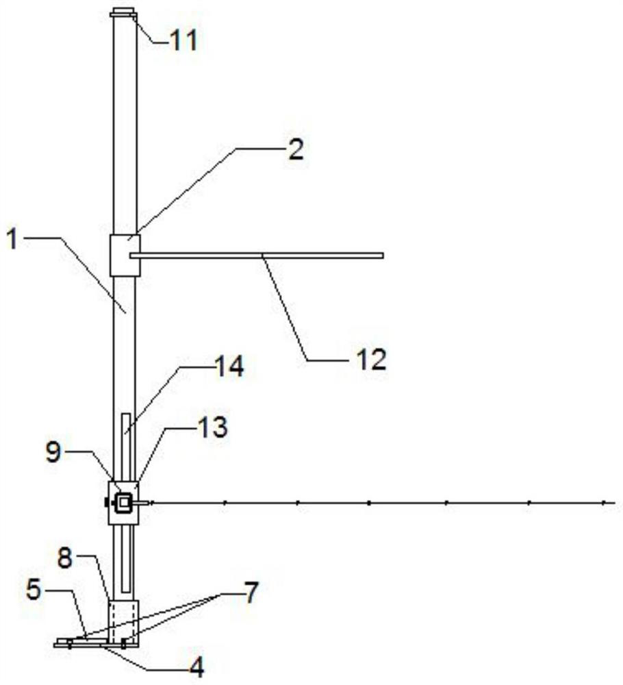
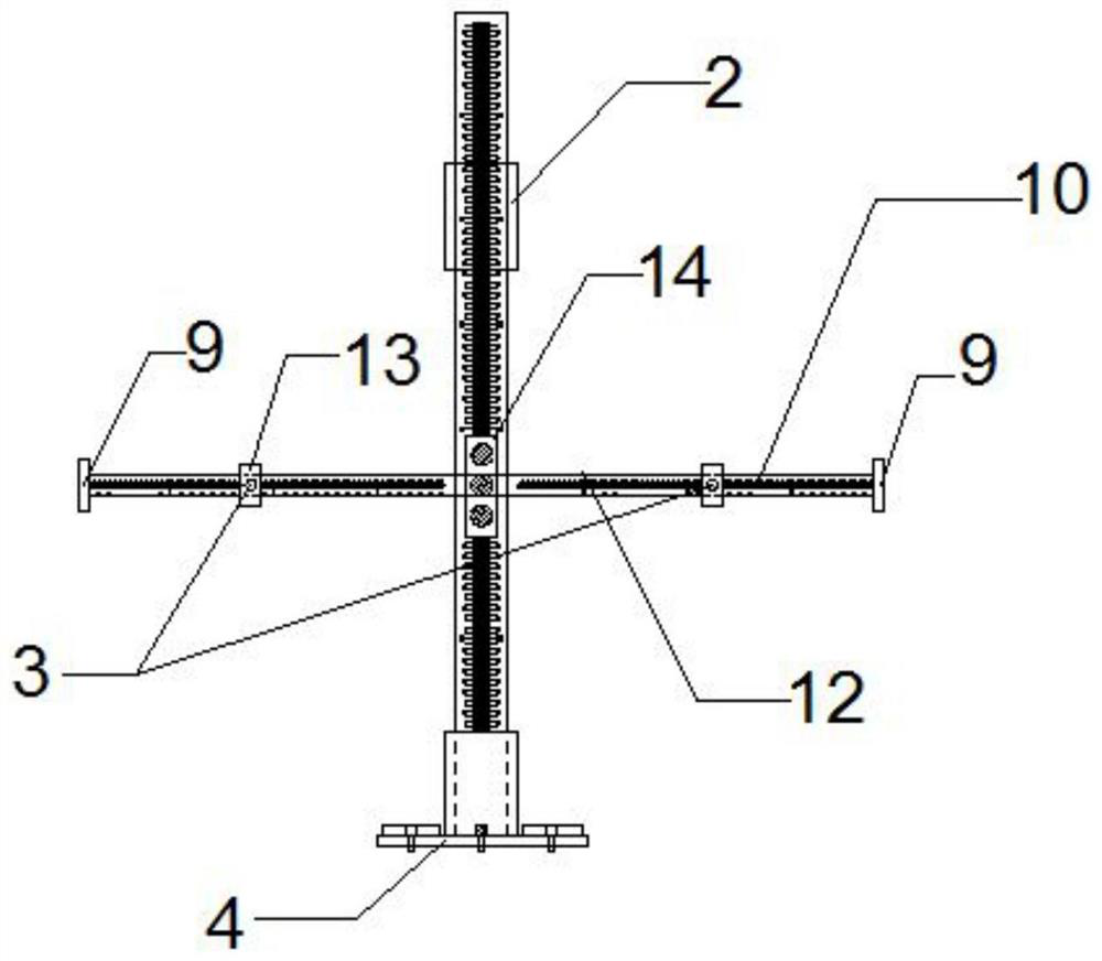
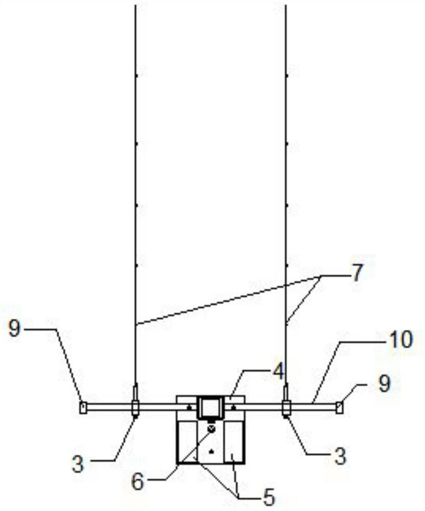
[0033] Such as Figure 1-4 As shown: a kind of scale rod device that can control the flatness of masonry includes a leveling base 4, a vertical rod 1 is fixedly connected to the leveling base 4, a horizontal rod 10 is fixedly connected to the vertical rod 1, and the horizontal rod 10 is connected to the vertical rod 1. Bars 1 are perpendicular to each other;

[0034] A first sleeve 2 is movably connected to the pole 1, the first sleeve 2 is located above the cross bar, and a longitudinal measuring rod 12 is fixedly connected to the first sleeve 2, and the longitudinal measuring rod 12 is perpendicular to the vertical pole 1;

[0035] A second sleeve 13 is movably connected to the cross bar 10, and there are two second sleeves 13, and a laser emitter 3 is mounted on the second sleeve 13.

[0036] Vertical bar 1, cross bar 10 and longitudinal measuring bar 12 are all scale rods, and vertical bar 1, cross bar 10 and longitudinal measuring bar 12 are telescopic bars.

[0037] Th...


PUM


Abstract

The invention discloses a laser height pole device capable of controlling the flatness of masonry. The laser height pole device capable of controlling the flatness of the masonry comprises a levelingbase, a vertical rod is fixedly connected to the leveling base, the vertical rod is perpendicular to the leveling base, and a cross rod is fixedly connected to the vertical rod. The cross rod and thevertical rod are perpendicular to each other; the vertical rod is movably connected with a sleeve, the sleeve is located above the cross rod, the sleeve is fixedly connected with a longitudinal measuring rod, the longitudinal measuring rod is perpendicular to the vertical rod, and a vertical rod limiting block is arranged at the top end of the vertical rod; the vertical rod, the cross rod and thelongitudinal measuring rod are all height poles, the vertical rod, the cross rod and the longitudinal measuring rod are all telescopic rods, and the leveling base is in bolted connection with a vertical rod inserting cylinder; and the vertical rod is fixedly connected with a leveling base plate through an inserting groove, the leveling base is in bolted connection with a counterweight, and the leveling base is in bolted connection with a horizontal air bubble meter. The laser height pole device capable of controlling the flatness of the masonry has the advantages of high precision, rich functions, simple operation, convenient carrying and use and the like. The laser height pole device capable of controlling the flatness of the masonry has the function of controlling the flatness of the masonry wall.

Description

technical field [0001] The invention belongs to the field of building construction, in particular to a laser marking rod device capable of controlling the flatness of masonry. Background technique [0002] At present, masonry work is an indispensable work in construction engineering. Today, with increasing labor costs and higher quality requirements, the quality of wall masonry and the control of wall flatness are particularly important. [0003] The traditional numbering rod either moves while laying, or controls both ends of the masonry with a line. The construction efficiency is low and the construction is inconvenient, especially in the case of a long wall. When the body wall is long, the line will be deflected, which will affect the accuracy of the masonry; and the line will be easily broken during the masonry process, which will affect the construction progress. [0004] In addition, the traditional measuring rod cannot control the flatness of the masonry wall, espec...

Claims


Application Information

Patent Timeline
Patent Type & Authority Applications(China)
IPC IPC(8): E04G21/18
CPCE04G21/18
Inventor 闫昊王志申书威刘远健刘宏泽
Owner CHINA MCC17 GRP
Why Eureka
Try Eureka