
Low-temperature heat storage device for comprehensive energy resource system

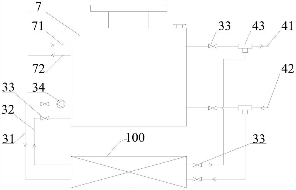
An integrated energy system and heat storage device technology, applied in the field of heat storage devices, can solve problems such as limiting the development of sensible heat storage technology, low heat storage density, unsuitable for long-term, large-capacity heat storage, etc.

Pending Publication Date: 2020-09-08
STATE GRID ECONOMIC TECH RES INST CO +1
View PDF0 Cites 0 Cited by
  • Summary
  • Abstract
  • Description
  • Claims
  • Application Information

AI Technical Summary

Problems solved by technology

However, since the sensible heat storage material relies on the temperature change of the heat storage material to store heat, the heat release process cannot be kept at a constant temperature, and the heat storage density is small, resulting in a large volume of heat storage equipment, low heat storage efficiency, and the presence of heat with the surrounding environment. The temperature difference will cause heat loss, and the heat cannot be stored for a long time. It is not suitable for long-term and large-capacity heat storage. At the same time, the low-grade energy of the heat storage material after heat release cannot be used, which limits the further development of sensible heat storage technology.
[0003] In summary, there are obviously inconveniences and defects in the actual use of the existing technology, so it is necessary to improve

Method used


Image

  • Low-temperature heat storage device for comprehensive energy resource system
  • Low-temperature heat storage device for comprehensive energy resource system
  • Low-temperature heat storage device for comprehensive energy resource system

Examples


Embodiment Construction

[0030] In order to make the objectives, technical solutions and advantages of the present invention clearer, the present invention will be described in further detail below in conjunction with the accompanying drawings and embodiments. It should be understood that the specific embodiments described here are only used to explain the present invention and are not intended to limit the invention.

[0031] It should be noted that, in the description of the present invention, terms such as "upper", "lower", "left", "right", "inner", "outer" and other indicated directions or positional relationships are based on the terms shown in the accompanying drawings. The direction or positional relationship shown is only for convenience of description, and does not indicate or imply that the device or element must have a specific orientation, be constructed and operated in a specific orientation, and thus should not be construed as limiting the present invention.

[0032] In addition, it shou...


PUM


Abstract

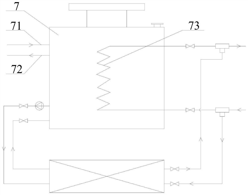
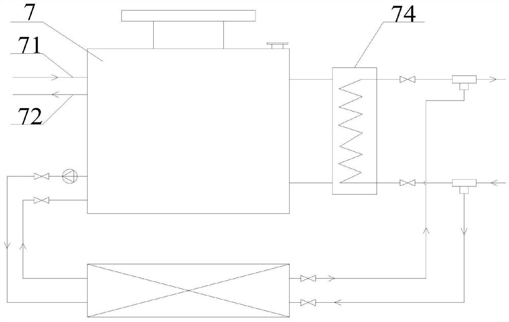
The invention relates to the technical field of a heat storage device, and provides a low-temperature heat storage device for a comprehensive energy resource system. The low-temperature heat storage device comprises a heat storage water tank, a water source heating pump and a circulation pump. When the heat storage water tank is high in temperature, heat is directly supplied through sensible heatof the heat storage water tank; when the water temperature is lower than the minimum requirement of supply water temperature of a user, heat cannot be directly supplied, and then the low grade heat storage water tank is used by the water source heating pump as a low temperature heating source, so that the purpose of further supplying heat from the heat storage water tank is achieved. The low-temperature heat storage device disclosed by the invention has the advantages that under the condition that under the same heat storage temperature difference, a design manner of coupling direct heat supply and indirect heat supply is adopted, so that compared with the heat storage water tank having the same size, the heat storage temperature is lower, compared with the heat storage water tank having the same required heat quantity, the heat storage size is lower, the heating source machine group efficiency and system synthesis efficiency are improved, heating quantity loss of the system is reduced, and a settlement measure which is more economic and convenient is provided for dilatation and reforming of a heat supply station.

Description

technical field [0001] The invention belongs to the technical field of heat storage devices, and in particular relates to a low-temperature heat storage device used in an integrated energy system. Background technique [0002] Sensible heat storage is a heat storage material that was widely used in the early stage because the process of heat storage and heat release is relatively simple. Sensible heat storage technology is the simplest and relatively mature among all heat storage materials. However, since the sensible heat storage material relies on the temperature change of the heat storage material to store heat, the heat release process cannot be kept at a constant temperature, and the heat storage density is small, resulting in a large volume of heat storage equipment, low heat storage efficiency, and the presence of heat with the surrounding environment. The temperature difference will cause heat loss, and the heat cannot be stored for a long time. It is not suitable f...

Claims


Application Information

Patent Timeline
IPC IPC(8): F24D15/02F24D15/04F24D17/00F24D17/02
CPCF24D15/02F24D15/04F24D17/0036F24D17/02
Inventor 王新雷田雪沁郭健翔王娜孙晋飞徐彤赵向明罗家松崔梦然宋崇明林钗红郭玉杰
Owner STATE GRID ECONOMIC TECH RES INST CO
Learn More