
Rotor of rotary electric machine

A technology for rotating motors and rotors, applied in the field of rotors, which can solve the problems that cannot be directly applied to SPM motors, and cannot properly cool the magnets

Active Publication Date: 2020-09-08
HONDA MOTOR CO LTD
View PDF9 Cites 3 Cited by
  • Summary
  • Abstract
  • Description
  • Claims
  • Application Information

AI Technical Summary

Problems solved by technology

[0006] The rotary electric machine described in Patent Document 1 is an IPM motor, so it cannot be directly applied to an SPM motor (Surface Permanent Magnet Motor, surface permanent magnet motor)
[0007] In addition, in the rotating electric machine of Patent Document 1, the cooling medium passes through the vicinity of the magnet and is discharged to the outer peripheral side, so there is a possibility that the magnet cannot be properly cooled.

Method used


Image

  • Rotor of rotary electric machine
  • Rotor of rotary electric machine
  • Rotor of rotary electric machine

Examples


Embodiment Construction

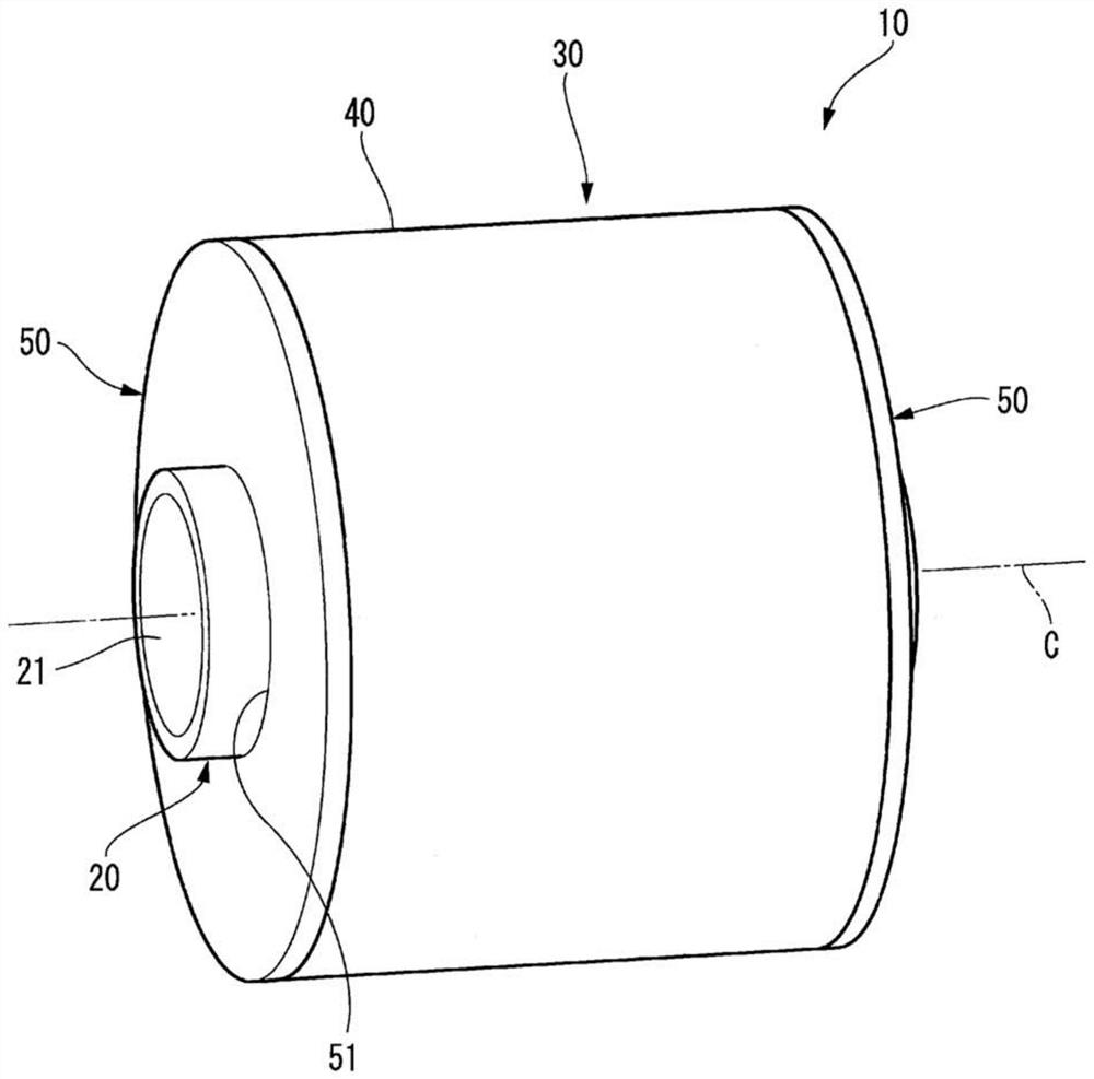
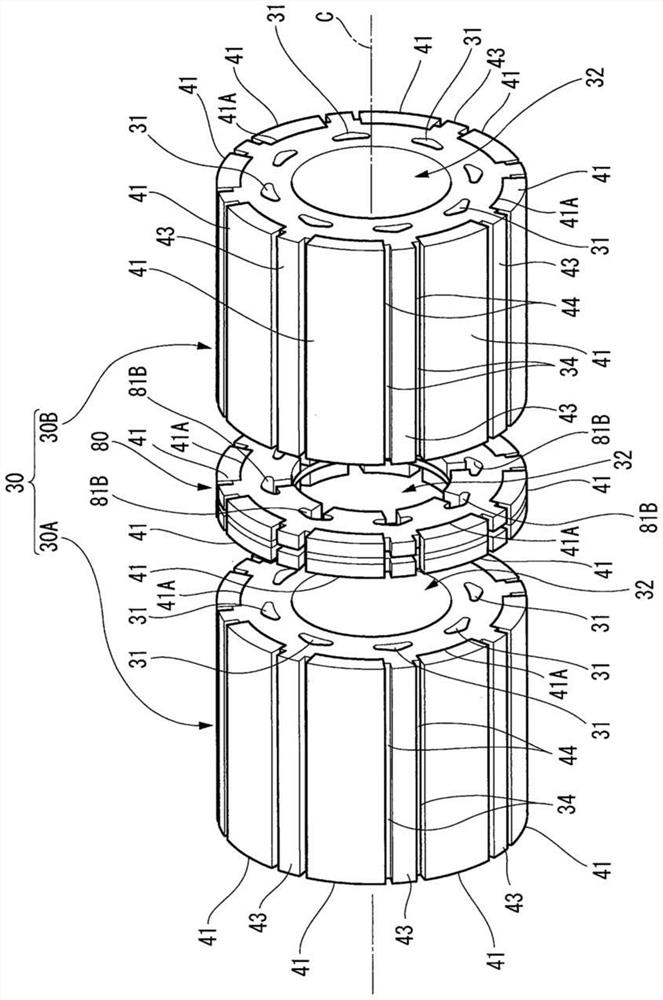
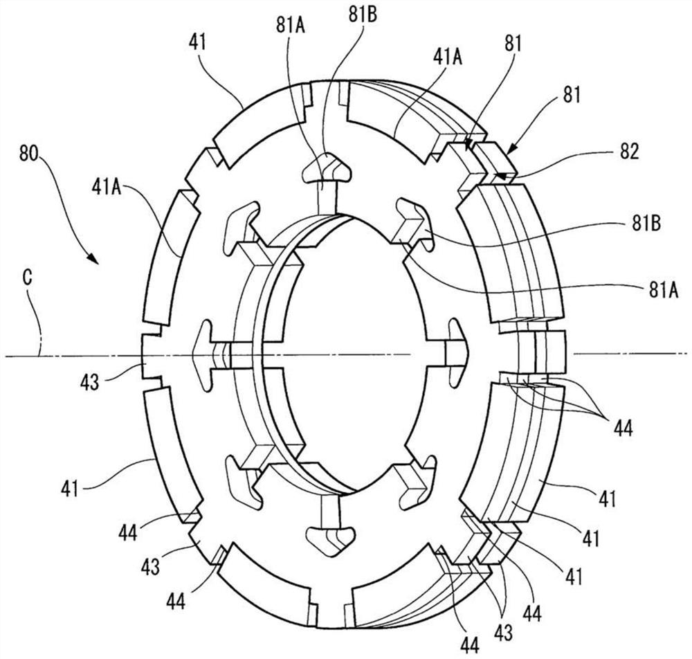
[0045] Below, refer to Figure 1 to Figure 7 One embodiment of the rotor of the rotating electrical machine of the present invention will be described.

[0046] In the following description, the rotation axis C refers to the axis at the center when the rotor 10 or the rotor shaft 20 of the rotating electric machine rotates, and the axial direction refers to a direction along the rotation axis C. In addition, the term "circumferential direction" refers to a direction in which a circle is drawn with the point as the center and along the circumference of the circle when the rotation axis C is viewed as a point. On the other hand, when it is called a radial direction, it means a direction from a point to a circle or a direction from a circle to a point. When called radially outward, it refers to the direction from the point toward the circle. When called radially inward, it refers to the direction from the circle toward the point.

[0047] Such as figure 1 and figure 2 As sh...


PUM


Abstract

The invention provides a rotor of a rotary electric machine. The rotor can be properly cool a magnet arranged on the periphery of a rotor core. The rotor core (30) is provided with: a plurality of magnet attaching grooves (41A) formed on the outer peripheral surface of the rotor core and in which the magnets (41) are disposed; an in-core flow path (31) extending inside the rotor core in an axial direction of the rotor core; and a refrigerant distribution plate (80). The refrigerant distribution plate includes: a first refrigerant distribution plate (81) in which an inner-diameter-side refrigerant flow path (21) extending from an in-shaft flow path toward the in-core flow path (81A) as viewed from the axial direction is formed; and a second refrigerant distribution plate (82) in which an outer-diameter-side refrigerant flow path (82A) extending from the in-core flow path toward the magnet attaching groove as viewed from the axial direction is formed. The first refrigerant distribution plate and the second refrigerant distribution plate are stacked in the axial direction.

Description

technical field [0001] The present invention relates to a rotor mounted in a rotating electrical machine such as an electric vehicle. Background technique [0002] In recent years, rotating electric machines are used in hybrid vehicles and EV vehicles. When the rotating electrical machine rotates, the temperature of the magnets which greatly affects the performance of the rotating electrical machine increases, and therefore appropriate cooling is required. [0003] Patent Document 1 describes that in an IPM motor (Interior Permanent Magnet Motor, an interior permanent magnet motor), a first plate having a first cooling medium passage and a second plate having a second cooling medium passage are stacked one by one. Constitutes the cooling medium distribution plate. [0004] prior art literature [0005] Patent Document 1: Japanese Patent Laid-Open No. 2017-070148 [0006] The rotary electric machine described in Patent Document 1 is an IPM motor, and therefore cannot be d...

Claims


Application Information

Patent Timeline
Patent Type & Authority Applications(China)
IPC IPC(8): H02K1/27H02K1/32
CPCH02K1/278H02K1/32H02K9/197H02K1/276
Inventor 落合祐介
Owner HONDA MOTOR CO LTD
Learn More