A sampling clock high-precision phase calibration and time reference determination method
A sampling clock and phase calibration technology, applied in satellite radio beacon positioning systems, digital transmission systems, instruments, etc., can solve the problems of receiver pseudo-range jump, failure to meet the establishment time and hold time, time relationship jump, etc. , to achieve the effect of eliminating random phase changes
- Summary
- Abstract
- Description
- Claims
- Application Information
AI Technical Summary
Problems solved by technology
Method used
Image
Examples
Embodiment 1
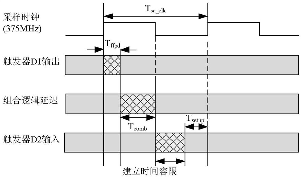
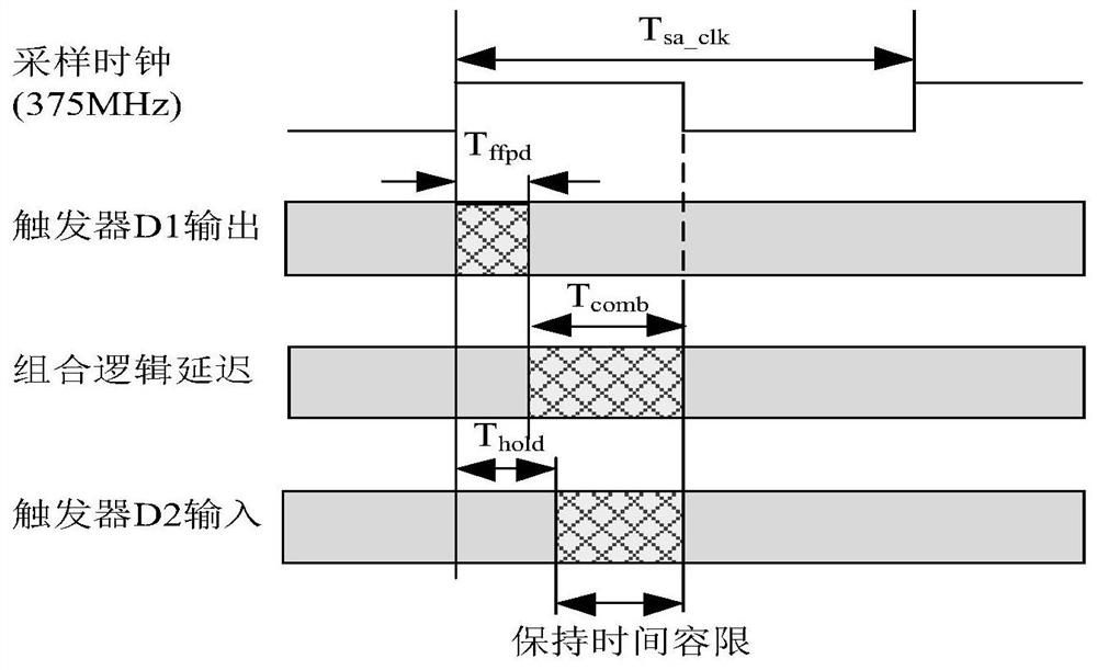
[0027] The application object of this embodiment is a satellite navigation ground station measurement communication system. The receiving terminal in the satellite navigation ground station measures the communication system by using the built-in frequency f osc The delay control module can implement (0.6+0.078*delay_value)ns delay control on the external input 1PPS signal, where delay_value is the delay counter value and 0≤delay_value≤31, then the minimum delay that can be achieved is 0.6ns, the maximum delay is 3.018ns. At the same time, the high-rate sampling clock frequency is f s , the period is 2.67ns, and the half period is 1.33ns.
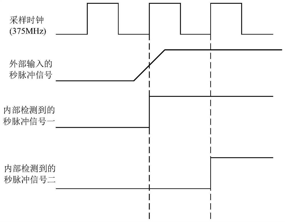
[0028] The delay control module performs the delay control on the externally input 1PPS signal to obtain a 1PPS delayed signal. Use a high-speed sampling clock to sample 1PPS delayed signals with different delay values. When the 1PPS delayed signal is detected by the high-rate sampling clock (f s ) phase jump occurs during sampling, obt...
Embodiment 2
[0032] refer to Figures 5 to 7 The method for high-precision phase calibration and time reference determination of a sampling clock comprises the following steps:
[0033] (1) First read the data transmitted by the digital signal processor and write it into the corresponding register.
[0034] (2) If the register controlling the phase calibration is enabled, perform step 3, otherwise, directly perform step 5.
[0035] (3) Obtain the value of the phase jump of the 1PPS delay signal sampling, and update the worst delay register. The specific steps are as Figure 6 Shown:
[0036] (3.1) The delay counter, clock counter and clock counter latch are all cleared to 0;
[0037] (3.2) Generate a 1PPS delay signal according to the delay formula (0.6+0.078*delay_value);
[0038] (3.3) using the rising edge of the 1PPS delay signal generated by the high-rate sampling clock detection step (3.2);
[0039] (3.4) obtain the corresponding clock counter value when step (3.3) detects the ...
PUM
 Abstract
Description
Claims
Application Information
 - R&D
- Intellectual Property
- Life Sciences
- Materials
- Tech Scout
- Unparalleled Data Quality
- Higher Quality Content
- 60% Fewer Hallucinations
Browse by: Latest US Patents, China's latest patents, Technical Efficacy Thesaurus, Application Domain, Technology Topic, Popular Technical Reports.
© 2025 PatSnap. All rights reserved.Legal|Privacy policy|Modern Slavery Act Transparency Statement|Sitemap|About US| Contact US: help@patsnap.com


