
Oil washing box for crank connecting rod bearing of internal combustion engine

A crank connecting rod and bearing oil technology, applied to chemical instruments and methods, cleaning methods and utensils, cleaning methods using liquids, etc., can solve problems such as affecting cleaning efficiency, troublesome control operations, and easy failures, and achieve improved cleaning Efficiency, control operation is convenient, and the effect of improving smoothness

Active Publication Date: 2020-09-11
临沂文衡信息技术有限公司
View PDF10 Cites 1 Cited by
  • Summary
  • Abstract
  • Description
  • Claims
  • Application Information

AI Technical Summary

Problems solved by technology

[0002] When assembling the internal combustion engine, the crank and connecting rod bearings need to be cleaned. Currently, when cleaning the crank and connecting rod bearings of the internal combustion engine, the lifting cleaning nozzle cooperates with the crank and connecting rod bearing conveying mechanism to carry out the conveying flow operation, but most of them are cleaned during cleaning. After the staff checks whether the position is aligned, then carry out the lifting control alignment cleaning, the control operation is troublesome, and the problem of inaccurate alignment is prone to occur, which affects the cleaning efficiency, or it can be realized through a complex sensor detection and control system. High, and the control is troublesome, and it is prone to failure

Method used


Image

  • Oil washing box for crank connecting rod bearing of internal combustion engine
  • Oil washing box for crank connecting rod bearing of internal combustion engine
  • Oil washing box for crank connecting rod bearing of internal combustion engine

Examples


Embodiment Construction

[0056] The following will clearly and completely describe the technical solutions in the embodiments of the present invention with reference to the accompanying drawings in the embodiments of the present invention. Obviously, the described embodiments are only some, not all, embodiments of the present invention.

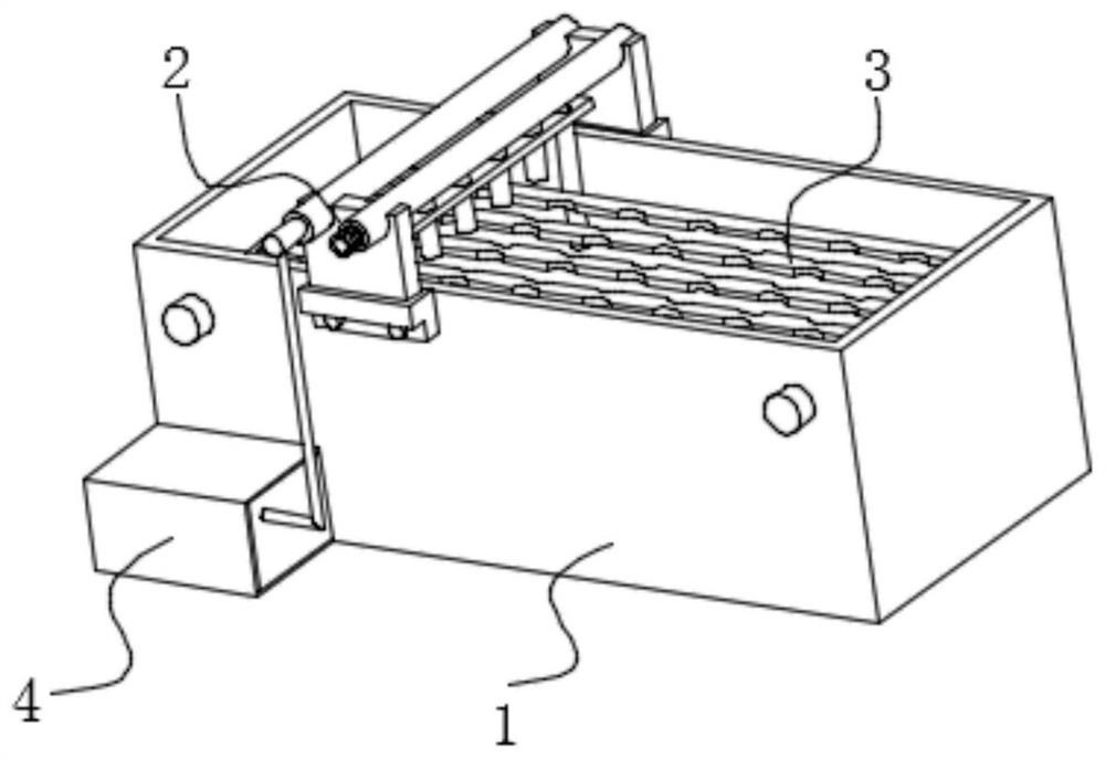
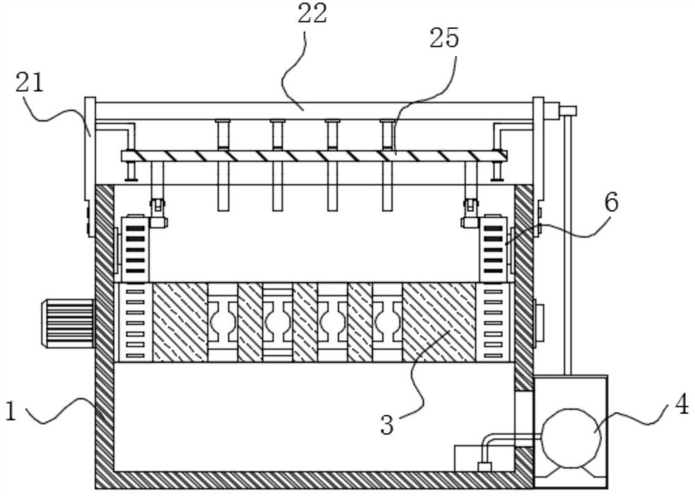
[0057] refer to Figure 1-15 , an internal combustion engine crank connecting rod bearing oil washing box, comprising: a cleaning box 1, a cleaning unit 2 for feeding and a linkage lifting drive mechanism 6;

[0058] The inner side of the cleaning box 1 is provided with a conveying mechanism 3 for conveying the connecting rod bearing along its length direction;

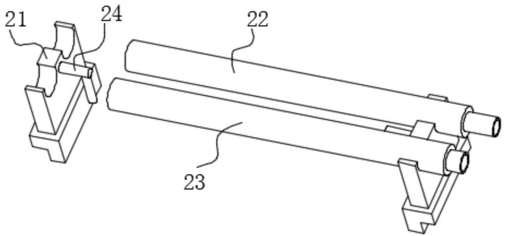
[0059] The feeding and cleaning unit 2 is composed of a feeding unit and a cleaning unit, and the feeding unit is erected at the opening position on the cleaning box 1, and the cleaning unit is movable up and down under the feeding unit;

[0060] The linked lifting drive mechanism 6 is arranged inside the c...


PUM


Abstract

The invention discloses an oil washing box for a crank connecting rod bearing of an internal combustion engine. The oil washing box comprises a cleaning box, a feeding and cleaning unit and a linkagelifting driving mechanism, wherein a conveying mechanism used for conveying the connecting rod bearing is arranged on the inner side of the cleaning box in the length direction of the cleaning box, the feeding and cleaning unit is composed of a feeding unit and a cleaning unit, the feeding unit is erected at the opening position of the cleaning box, and the cleaning unit is movably arranged belowthe feeding unit in a lifting mode. According to the oil washing box for the crank connecting rod bearing of the internal combustion engine, by arranging the linkage lifting driving mechanism, the effect that the conveying mechanism on the inner side of the cleaning box moves to be matched with the linkage lifting driving mechanism to drive the cleaning unit to automatically ascend and descend ina reciprocating mode is achieved, and finally, the effect that the cleaning unit is automatically controlled to conduct alignment lifting cleaning by intermittently controlling the conveying mechanismis achieved, so that workers have no need watching and performing manual alignment, meanwhile, the situation that a complex sensor detection control system is needed for achieving the effects is avoided, control operation is convenient, and the cleaning efficiency is remarkably improved.

Description

technical field [0001] The invention relates to the technical field of a crank connecting rod bearing cleaning box, in particular to an internal combustion engine crank connecting rod bearing oil washing box. Background technique [0002] When assembling the internal combustion engine, the crank and connecting rod bearings need to be cleaned. Currently, when cleaning the crank and connecting rod bearings of the internal combustion engine, the lifting cleaning nozzle cooperates with the crank and connecting rod bearing conveying mechanism to carry out the conveying flow operation, but most of them are cleaned during cleaning. After the staff checks whether the position is aligned, then carry out the lifting control alignment cleaning, the control operation is troublesome, and the problem of inaccurate alignment is prone to occur, which affects the cleaning efficiency, or it can be realized through a complex sensor detection and control system. High, and the control is trouble...

Claims


Application Information

Patent Timeline
IPC IPC(8): B08B3/02B08B3/08B08B5/02B08B13/00
CPCB08B3/022B08B3/024B08B3/08B08B5/023B08B13/00
Inventor 尤建国
Owner 临沂文衡信息技术有限公司
Learn More