Reciprocating intelligent high-efficiency presser

A reciprocating and pressing technology, applied in the field of reciprocating intelligent high-efficiency presses, can solve the problems of low production efficiency and complicated operation, and achieve the effects of improving work efficiency, improving product quality and reducing production costs.

Inactive Publication Date: 2020-09-11
孔彩艳
View PDF6 Cites 2 Cited by
  • Summary
  • Abstract
  • Description
  • Claims
  • Application Information

AI Technical Summary

Problems solved by technology

[0005] The purpose of the present invention is to provide a reciprocating intelligent high-efficiency press machine with simple operation and high-efficiency production for the above-mentioned problems of cumbersome operation and low production efficiency

Method used


Image

  • Reciprocating intelligent high-efficiency presser
  • Reciprocating intelligent high-efficiency presser
  • Reciprocating intelligent high-efficiency presser

Examples


Embodiment 1

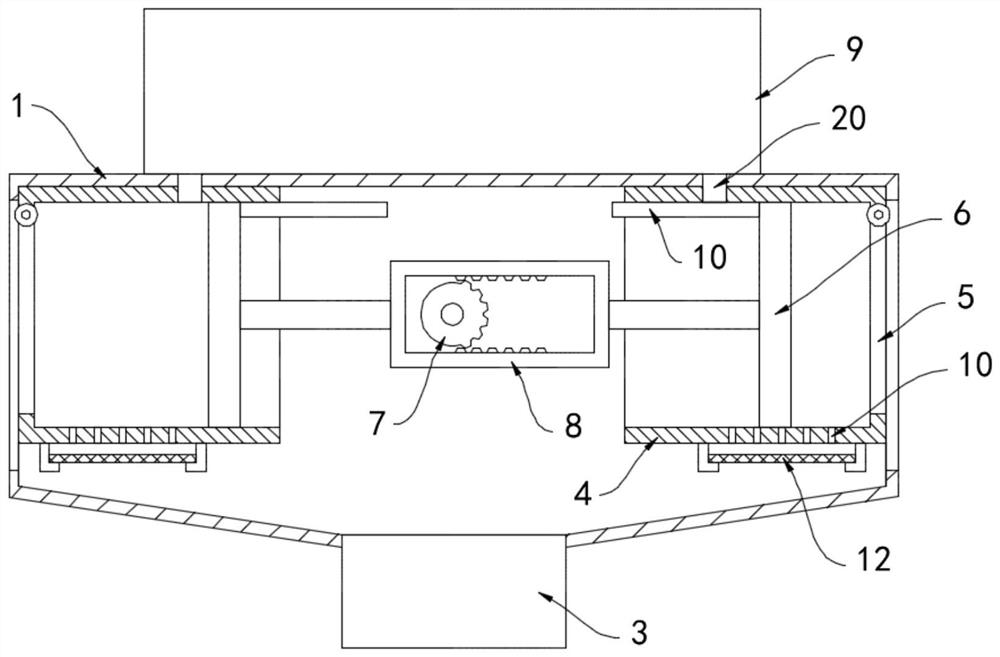
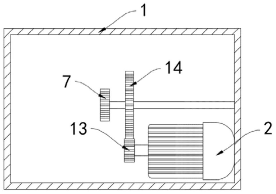
[0022] Such as Figure 1-2 As shown, a reciprocating intelligent high-efficiency press includes a housing 1 and a motor 2 installed in the housing 1. Both ends of the housing 1 are open, and the lower end of the housing 1 is equipped with an oil sump 3. The housing The bottom surface of 1 is provided with a downwardly concave arc surface, which is convenient for the squeezed vegetable oil to flow into the oil collection tank 3 .

[0023] The inner walls of both sides of the housing 1 are fixedly connected with an oil extraction cylinder 4, and the side walls of the oil extraction cylinder 4 are hinged with a discharge door 5. There is a vertically arranged pressure plate 6 sliding horizontally in the oil extraction cylinder 4, and the motor 2. A half gear 7 is connected through a reduction mechanism. The reduction mechanism includes a drive gear 13 fixed coaxially with the output shaft of the motor 2. A reduction gear 14 is coaxially fixed on one side of the half gear 7. The r...

Embodiment 2

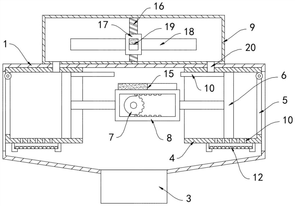
[0030] Such as image 3 As shown, the difference between this embodiment and Embodiment 1 is that the upper end of the movable frame 8 is provided with a bar magnet 15, and the two ends of the bar magnet 15 have opposite magnetic poles, and a vertically arranged magnet is fixedly installed in the storage box 9. Screw mandrel 16, screw mandrel 16 external threads are sleeved with screw mandrel nut 17, two push plates 18 are installed on the side wall of screw mandrel nut 17, and the lower end of screw mandrel nut 17 is fixedly connected with the permanent that matches with bar magnet 15. Magnetic block 19, the upper and lower ends of the permanent magnet block 19 have opposite magnetic poles.

[0031] In this embodiment, the bar magnet 15 can move back and forth with the movable frame 8, and then the opposite ends of the bar magnet 15 with magnetic poles alternately move to the right below the permanent magnet block 19 to generate periodic changes in the attraction of the perma...


PUM


Abstract

The invention belongs to the field of pressers and particularly relates to a reciprocating intelligent high-efficiency presser. The reciprocating intelligent high-efficiency presser comprises a shelland a motor mounted in the shell. The two ends of the shell are provided with openings. An oil collection tank is mounted at the lower end of the shell. The inner sidewalls of the two sides of the shell are both fixedly connected with oil pressing barrels. A discharge door is hinged to the sidewall of each oil pressing barrel. A pressure plate arranged vertically is horizontally and slidably arranged in each oil pressing barrel. The motor is connected with a half-gear through a speed reducer. The half-gear is externally sleeved with a moving frame. The inner top surface and the inner bottom surface of the moving frame are both provided with tooth grooves. The half-gear is engaged with the moving frame. The two ends of the moving frame are fixedly connected with the two pressure plates through connecting rods. According to the reciprocating intelligent high-efficiency presser, the motor can drive the moving frame to alternately push the pressure plates on the two sides to press oil materials in the oil pressing barrels on the two sides. The moving frame conducts pressing operation in the whole travel distance. Energy waste is avoided. The working efficiency is improved, and the production cost is reduced.

Description

technical field [0001] The invention belongs to the field of squeezing machines, in particular to a reciprocating intelligent high-efficiency squeezing machine. Background technique [0002] Oil extraction by pressing is a method of extracting oil from the oil by means of mechanical force. According to the depth of oil extraction and the pressure on the material during pressing, oil extraction can be divided into one-time pressing and leaching oil extraction. Compared with other oil extraction methods, combined pre-pressing and pressing oil extraction have the advantages of simple process, less supporting equipment, strong adaptability to oil species, flexible production, good oil quality, light color, and pure flavor. [0003] During the oil extraction process of the traditional press, due to the fixed internal volume of the press, the oil plants need to be pressed in batches. After each press is completed, the press needs to be stopped to remove the oil cake and add oil pl...

Claims


Application Information

Patent Timeline
Patent Type & Authority Applications(China)
IPC IPC(8): B30B9/06B30B9/26B30B15/30B01D29/03C11B1/06
CPCB01D29/03B30B9/06B30B9/26B30B15/30C11B1/06
Inventor 孔彩艳
Owner 孔彩艳
Why Eureka
Try Eureka