High-speed multi-bag synchronous vacuum shaping packaging machine

A packaging machine and vacuum technology, applied in packaging, transportation packaging, transportation and packaging, etc., can solve the problems of reducing operating speed and affecting packaging output, and achieve the effect of saving floor space, saving waiting time, and improving equipment packaging production capacity

Pending Publication Date: 2020-09-11
福建宇杰自动化科技有限公司
0 Cites 2 Cited by

AI-Extracted Technical Summary

Problems solved by technology

[0002] Existing packaging machines for granular items, such as rice, tea, and vacuum food packaging machines, generally adopt vacuum-pumping and shaping in a vacuum box an...

Method used

3) As shown in Figure 2, the finished product is delivered to the discharge conveyor belt 9 by the finished product in cooperation with the buffer mechanism 8 by the receiving bag mechanism 7, and the bag clamping mechanis...

Abstract

The invention discloses a high-speed multi-bag synchronous vacuum shaping packaging machine. The machine comprises a rack; the rack is provided with at least two vacuum shaping devices which work independent of each other; filling mechanisms are arranged at the top of the rack and correspond to work stations respectively; overturning mechanisms are arranged on the work stations and below the corresponding filling mechanisms; a vacuum shaping mechanism is arranged right above the overturning mechanisms and can move up and down along the vertical direction; each of the overturning mechanisms comprises a rotating sealing mechanism and an electric rotation driving mechanism, the rotating sealing mechanism is arranged at one end of an overturning plate and is adjustable in height, the electricrotation driving mechanism drives the overturning plate to rotate, and a discharging transportation belt is arranged below the overturning plate; a package receiving mechanism is arranged at a feedingend of the discharging transportation belt; and the package receiving mechanism receives a packaged product from the overturning plate and transfers the same to the discharging transportation belt. The rotating sealing mechanism realizes high-speed operation of packaging equipment and improves packaging productivity of the equipment. Furthermore, a plurality of high-efficiency vacuum shaping devices are combined and work synchronously, so the packaging productivity of the equipment is further improved and occupied space is saved.

Application Domain

Packaging by pressurising/gasifyingWrapper twisting/gathering

Technology Topic

Electrical and Electronics engineeringPackaging machine

Image

  • High-speed multi-bag synchronous vacuum shaping packaging machine
  • High-speed multi-bag synchronous vacuum shaping packaging machine
  • High-speed multi-bag synchronous vacuum shaping packaging machine

Examples

  • Experimental program(1)

Example Embodiment

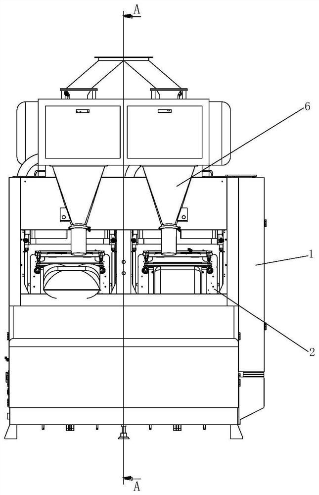
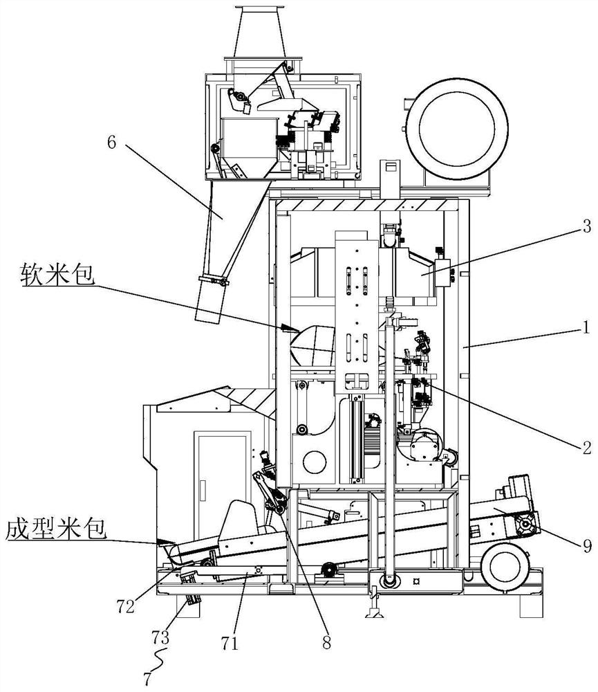
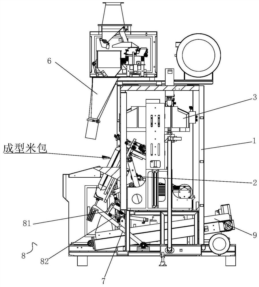
[0023] Such as Figure 1-6 As shown in one, the high-speed multi-bag synchronous vacuum shaping packaging machine of the present invention includes a frame 1. The frame 1 has at least two independent working stations, and the top of the frame 1 is respectively provided with each station The filling mechanism 6 is provided with a turning mechanism 2 at each station and below the corresponding filling mechanism 6, and a vacuum shaping mechanism 3 that can move up and down in the vertical direction is provided above the turning mechanism 2; the turning mechanism 2 Including a turning plate 21 and an electric drive mechanism 22 that drives the turning plate 21 to rotate. A discharge conveyor belt 9 is provided under the turning plate 21. A rotary sealing mechanism 4 is provided on one end of the turning plate 21 to rotate and seal. The mechanism 4 includes a base 41 and a rotating base 42, one end of the rotating base 42 is rotatably connected to one end of the base 41, the rotating base 42 is driven to rotate by a rotating drive cylinder 43, and the bottom of the other end of the rotating base 42 is fixed with a heat seal The bead 44, the other end of the base 41 is provided with a silicone bottom plate 45 corresponding to the heat-sealed bead 44, and a bag clamping mechanism 5 is provided on the inward end of the base 41. The bag clamping mechanism 5 includes a bag clamping bar 51 and a driving bag clamping bar 51 is composed of a bag clamping cylinder 52 that moves up and down in the vertical direction.
[0024] The base 41 is connected to an electric lifting mechanism 46, and the electric lifting mechanism 46 is used to adjust the height position of the base 41 to meet the production requirements of different specifications. In this embodiment, the electric lifting mechanism 46 is composed of an electric push rod and an air cylinder.
[0025] A first support arm 23 is rotatably connected to one end of the bottom of the flip plate 21, and a second support arm 24 is rotatably connected to the other end of the bottom of the flip plate 21. The electric drive mechanism 22 includes a reduction motor 221, a crank 222 and a connecting rod 223. One end of the crank 222 is rotatably connected with the output shaft of the reduction motor 221, and the other end of the crank 222 is rotatably connected with one end of the connecting rod 223. The other end of the rod 223 is rotatably connected with the middle of the first support arm 23, and the output shaft of the reduction motor 221 rotates to drive the flip plate 21 to flip forward or flip to a horizontal position.
[0026] The loading end of the discharging conveyor belt 9 is provided with a package receiving mechanism 7, and the package receiving mechanism 7 receives the packaged products on the turning plate 21 and transfers it to the discharge conveyor belt 9.
[0027] The vacuum shaping mechanism 3 includes a vacuum cover that can move in a vertical direction (generally, a cylinder is used to drive up and down). The top of the vacuum cover is connected with a vacuum tube for vacuuming its interior. The inside of the vacuum cover is capable of moving up and down in the vertical direction. The movable shaping plate can be lifted and lowered by airbags.
[0028] A shaping bottom plate 25 is connected to the upper end surface of the turning plate 21, and the bottom of the shaping bottom plate 25 is provided with a vibration motor 26 for driving its vibration. The shaping bottom plate 25 is matched with the shaping pressing plate in the vacuum cover, and under the action of the vibration motor 26, the shaping effect of the packaged product can be improved.
[0029] The bag receiving mechanism 7 includes a swing arm 71, a carrier plate 72, and a carrier cylinder 73. One end of the swing arm 71 is rotatably connected to the frame 1 and is driven to rotate by a first driving cylinder. The carrier cylinder 73 is fixed on the other end of the swing arm 71, and the end of the push rod of the carrier cylinder 73 is fixedly connected to the bottom of the carrier plate 72. In addition, a buffer mechanism 8 is provided on the loading end of the discharging conveyor belt 9. The buffer mechanism 8 includes a buffer rod 81 and a second driving cylinder 82. One end of the buffer rod 81 is rotatably connected to the frame 1. , The second driving cylinder 82 drives the buffer rod 81 to rotate. After the packaged product is shaped and sealed, the turning plate 21 is turned forward. At this time, the swing arm 71 rotates and rises and the towing cylinder 73 lifts the towing plate 72, the packaged product falls onto the towing plate 72, and then the swing arm 71 rotates The descending drives the packaged product to fall onto the loading end of the discharging conveyor belt 9. In the process of the swing arm 71 rotating and descending, the second driving cylinder 82 drives the buffer rod 81 to swing out and lean against the packaged product. During the descending process of the swing arm 71, the buffer rod 81 is gradually retracted, so that the packaged products are slowly and safely sent onto the discharge conveyor belt 9.
[0030] The working process of the present invention is as follows (taking rice packaging as an example):
[0031] 1) Such as Figure 4 As shown, the packaging bag is filled with a predetermined amount of rice on the filling mechanism 6, and then the rice bag is clamped and fixed on the bag clamping mechanism 5, and then the turning plate 21 is turned to the horizontal position;
[0032] 2) The vacuum shaping mechanism 3 is pressed down on the turning plate 21, and the vacuum pump starts to vacuum. When the vacuum degree inside the rice bag is in place, the rotary sealing mechanism 4 rotates and seals. While sealing, the vacuum shaping mechanism 3 rises. After the sealing is completed, such as image 3 As shown, the bag clamping mechanism 5 is opened, the turning plate 21 is turned forward, and the bag receiving mechanism 7 rises to catch the rice bag;
[0033] 3) Such as figure 2 As shown, the package receiving mechanism 7 cooperates with the buffer mechanism 8 to send the finished product onto the discharge conveyor belt 9, and at the same time, the bag clamping mechanism 5 on the turning plate 21 clamps a package of filled packaging bags and turns to the horizontal vacuum station to enter The next working cycle realizes the high-speed operation of the packaging equipment.
[0034] The implementation of the present invention is described above in conjunction with the accompanying drawings, but the present invention is not limited to the above specific embodiments. The above specific embodiments are illustrative rather than limiting the present invention. Those of ordinary skill in the art should understand that: Modifications to the technical solutions described in the foregoing embodiments, or equivalent replacement of some or all of the technical features; these modifications or replacements do not cause the essence of the corresponding technical solutions to deviate from the scope of the technical solutions of the embodiments of the present invention. All of them shall be covered in the scope of the claims and specification of the present invention.

PUM

no PUM

Description & Claims & Application Information

We can also present the details of the Description, Claims and Application information to help users get a comprehensive understanding of the technical details of the patent, such as background art, summary of invention, brief description of drawings, description of embodiments, and other original content. On the other hand, users can also determine the specific scope of protection of the technology through the list of claims; as well as understand the changes in the life cycle of the technology with the presentation of the patent timeline. Login to view more.

Similar technology patents

Rapid car taking system and method

Owner:SHENZHEN SHENGLU IOT COMM TECH CO LTD

Application level speculative processing

ActiveUS20130111501A1reduce waiting timeavoids requirement
Owner:AUTODESK INC

Video propagating method and device

Owner:深圳劲嘉盒知科技有限公司

Service reservation-based node recommendation method, terminal device and medium

InactiveCN109190038Areduce waiting timeImprove customer experience
Owner:CHINA CONSTRUCTION BANK

Classification and recommendation of technical efficacy words

Why Eureka
Try Eureka