
Cable stretching device used for power grid construction

A cable and power grid technology, which is applied in the field of cable tensioning devices for power grid construction, can solve the problems of reducing the efficiency of winding, long winding time, and excessive looseness.

Active Publication Date: 2020-09-11
STATE GRID BEIJING ELECTRIC POWER +2
View PDF13 Cites 4 Cited by
  • Summary
  • Abstract
  • Description
  • Claims
  • Application Information

AI Technical Summary

Problems solved by technology

[0002] In the construction of transmission lines, wire erection construction is one of the most critical construction processes, and the deployment of guide ropes is the main content of the construction process. More and more deployment and deployment of guide ropes are carried out by powered parachute light aircraft. , after the powered parachute light aircraft is released to the wire tower, it needs to be pulled by a stretching device. At present, when the existing stretching device is pulling, the motor drives the winding roller to rotate to realize automatic winding, but the automatic It is difficult to effectively control the tension of the cable by winding, which leads to the problem that the cable is installed too tight or too loose, which affects the normal use of the cable. In addition, the existing stretching device can only One cable is rewound, and the overall rewinding time is long, which greatly reduces the efficiency of rewinding, so it is necessary to improve the existing technology to solve the above problems

Method used


Image

  • Cable stretching device used for power grid construction
  • Cable stretching device used for power grid construction
  • Cable stretching device used for power grid construction

Examples


Embodiment 1

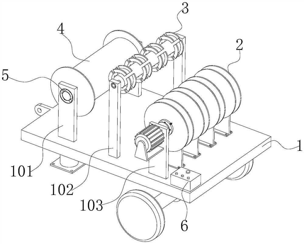
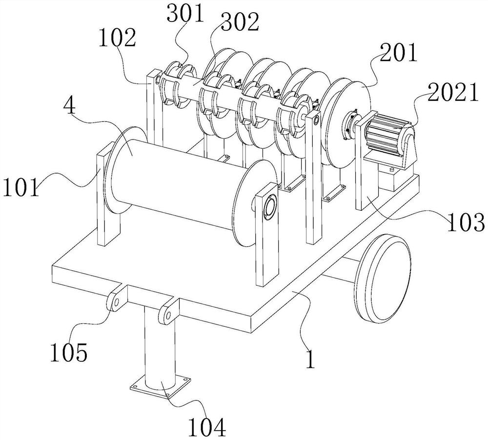
[0048] see Figure 1-2 As shown, the present invention is a cable stretching device for power grid construction, including a moving car body 1, a winding mechanism 2, a detection mechanism 3 and a guiding mechanism 4. It can be seen from the accompanying drawings that the above-mentioned components constitute the main body of the device. The basic composition is that a winding mechanism 2 and a guiding mechanism 4 are respectively arranged on both sides above the moving vehicle body 1, and a detection mechanism 3 is arranged above the position between the winding mechanism 2 and the guiding mechanism 4, and the winding mechanism 2 is set for For the winding of the cable, the guiding mechanism 4 is set to guide the cable when winding, and the detection mechanism 3 is set to detect the tension of the cable when winding;

[0049] Both sides of one end face of the mobile car body 1 are symmetrically provided with hanging lugs 105, and the setting of the hanging lugs 105 is used to...


PUM


Abstract

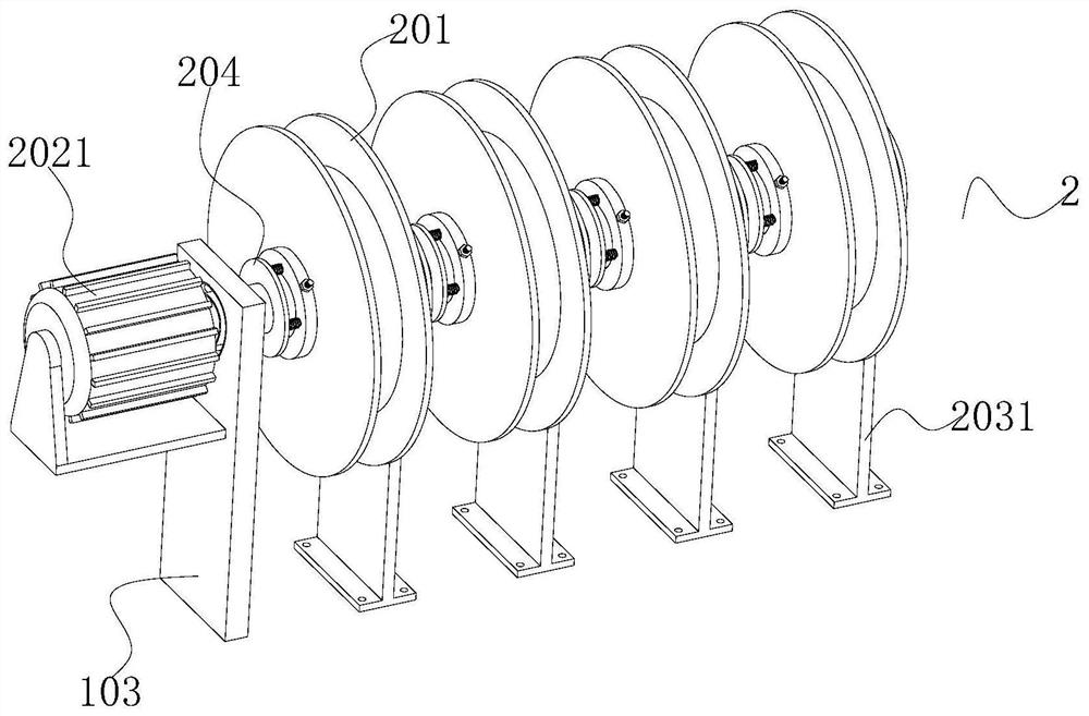
The invention discloses a cable stretching device used for power grid construction, and relates to the technical field of power grid construction. The cable stretching device comprises a movable vehicle body, a winding mechanism, a detection mechanism and a guide mechanism. The winding mechanism and the guide mechanism are arranged on the two sides of the portion above the movable vehicle body correspondingly. The detection mechanism is arranged above the position between the winding mechanism and the guide mechanism The winding mechanism comprises winding rollers, a rotating shaft, a brake mechanism and a drive mechanism. The multiple winding rollers are arranged side by side and are all arranged on the rotating shaft in a sliding and sleeving manner. The brake mechanism and the drive mechanism are arranged on the two sides of the winding rollers in a concentric manner correspondingly. By means of arrangement of the winding rollers, pressure sensors, arc-shaped guide frames, the brakemechanism and the drive mechanism and cooperation between structures, when the device is used, the tension degree of cables can be monitored and controlled in real time, stretching of multiple cablescan be controlled through the device at the same time, the work efficiency is greatly improved, and labor force is reduced.

Description

technical field [0001] The invention belongs to the technical field of power grid construction, and in particular relates to a cable stretching device for power grid construction, which is mainly used for stretching the cables when the cables are erected. Background technique [0002] In the construction of transmission lines, wire erection construction is one of the most critical construction processes, and the deployment of guide ropes is the main content of the construction process. More and more deployment and deployment of guide ropes are carried out by powered parachute light aircraft. , after the powered parachute light aircraft is released to the wire tower, it needs to be pulled by a stretching device. At present, when the existing stretching device is pulling, the motor drives the winding roller to rotate to realize automatic winding, but the automatic It is difficult to effectively control the tension of the cable by winding, which leads to the problem that the ca...

Claims


Application Information

Patent Timeline
Patent Type & Authority Applications(China)
IPC IPC(8): B65H54/44B65H57/14B65H54/20B65H59/38
CPCB65H54/20B65H54/44B65H57/14B65H59/385B65H2701/34
Inventor 朱来友
Owner STATE GRID BEIJING ELECTRIC POWER
Learn More