Winding device of magnetic levitation motor core

A technology of magnetic levitation and movement, applied in electromechanical devices, manufacturing motor generators, electrical components, etc., can solve the problems of low winding efficiency of copper wire

Active Publication Date: 2020-04-14
广东三奇实业发展有限公司
View PDF9 Cites 6 Cited by
  • Summary
  • Abstract
  • Description
  • Claims
  • Application Information

AI Technical Summary

Problems solved by technology

[0002] The magnetic levitation motor uses the core coil installed on the machine base to induce a magnetic field in the rotating rotor, and levitates the rotating rotor through the interaction of the stator and rotor magnetic fields, avoiding the contact friction between the shaft and the bearing of the traditional motor. Due to mechanical problems, the speed of the motor is not limited by the bearings. The core needs to be wound with multiple coils of copper wire. The current winding device fixes the polarity of the core and manually winds the copper wire around the winding post on the core. Or fix the movement and rotate it through the base, and guide the copper wire manually, so that the copper wire is accurately wound on the winding column, and the winding efficiency of the copper wire is low. Therefore, we propose a winding of the magnetic levitation motor movement system to solve the above problems

Method used


Image

  • Winding device of magnetic levitation motor core
  • Winding device of magnetic levitation motor core
  • Winding device of magnetic levitation motor core

Examples


Embodiment Construction

[0015] The following will clearly and completely describe the technical solutions in the embodiments of the present invention with reference to the accompanying drawings in the embodiments of the present invention. Obviously, the described embodiments are only some, not all, embodiments of the present invention. Based on the embodiments of the present invention, all other embodiments obtained by persons of ordinary skill in the art without making creative efforts belong to the protection scope of the present invention.

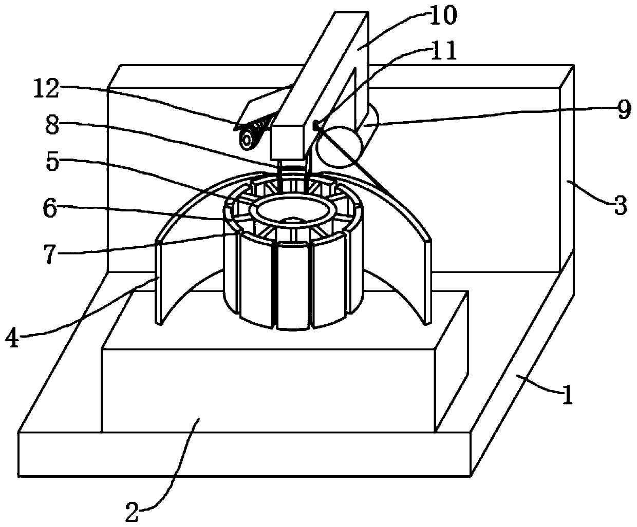
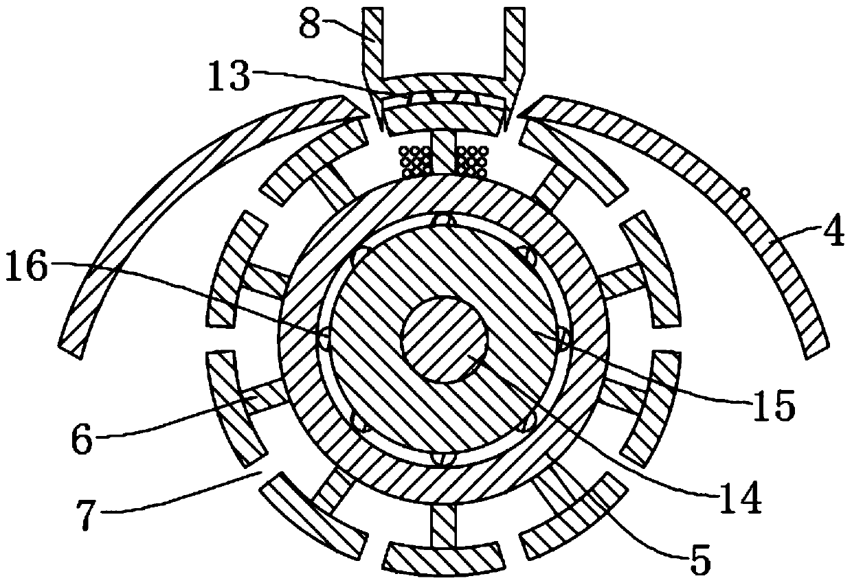
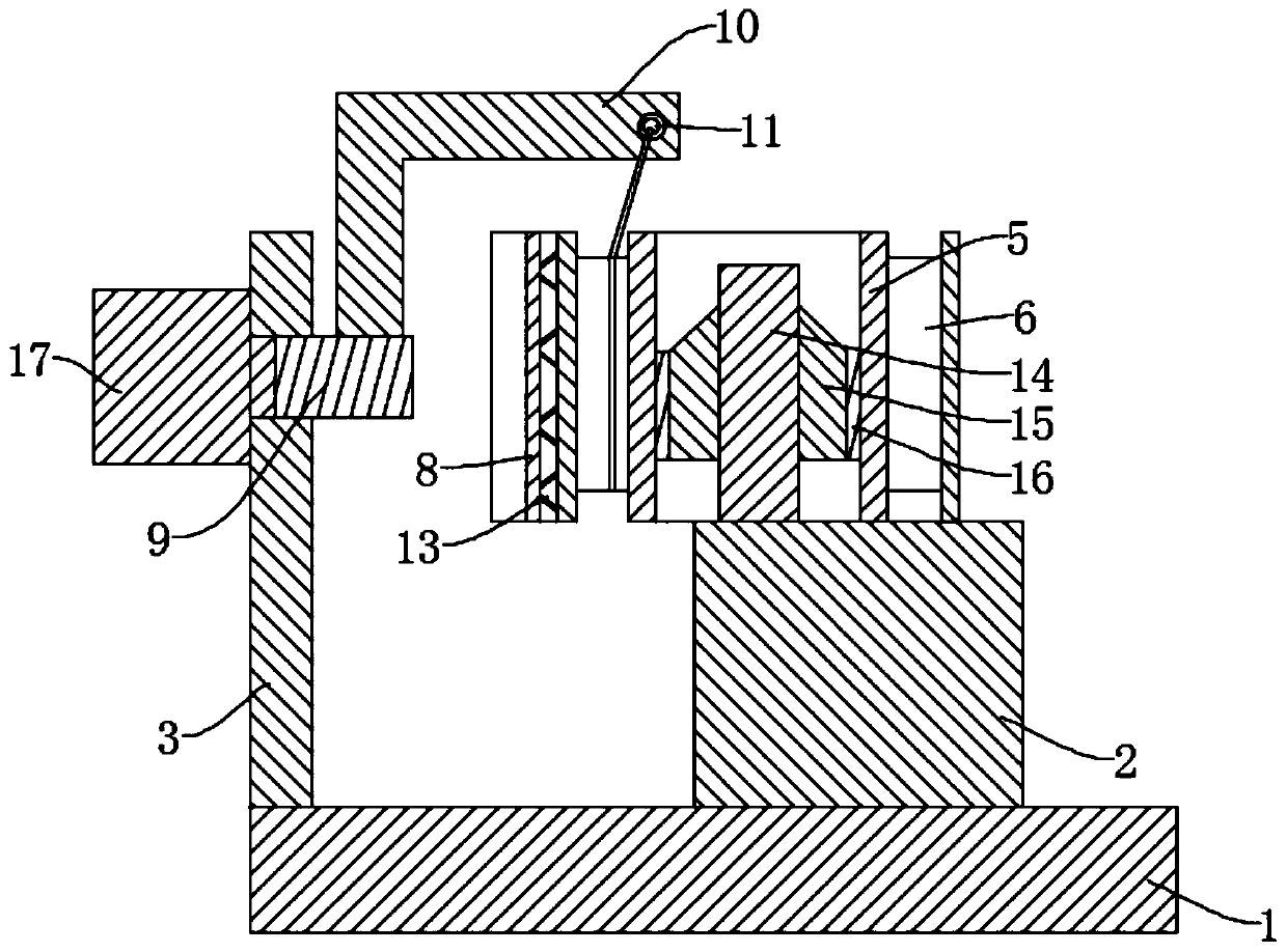
[0016] see Figure 1-4 , the present invention provides a technical solution: a winding device for a magnetic levitation motor core, including a base 1, one side of the base 1 is fixedly installed with a mounting platform 2, the middle part of the mounting platform 2 is fixedly installed with a fixed column 14, and the fixed column 14 is fixed Sleeve the positioning column 15, the outer side of the positioning column 15 is socketed with the core 5, and a plura...


PUM


Abstract

The invention discloses a winding device of a magnetic levitation motor core, which comprises a base, a mounting table is mounted on one side of base, a fixing column is mounted on the mounting table,the fixed column is sleeved with a positioning column; a machine core is sleeved on the positioning column; a plurality of wrapping posts are arranged on the surface of the machine core; a wire inletis formed between every two adjacent wrapping posts; guide plates are mounted at two ends of the mounting table; one end of the guide plate is located at the wire inlet, a clamping plate is clamped on the winding column between the end faces of the guide plate, a rotating shaft is sleeved on the vertical plate, a motor is installed on the vertical plate, an output shaft of the motor is connectedwith the rotating shaft, a winding rod is installed on the outer wall of the rotating shaft, a copper wire coil is installed on the side wall of the winding rod, a thread hole is arranged at the winding rod, and a copper wire on the copper wire coil penetrates the thread hole and wound on the winding rod. The motor drives the rotating shaft to rotate, the winding rod rotates around the machine core, the copper wire slides to the wire inlet along the outer wall of the guide plate when the winding rod rotates, the copper wire is separated from the guide plate and then makes contact with the outer wall of the clamping plate, the outer wall of the clamping plate is further guided to slide into the wire inlet, the copper wire is wound around the winding column, and automatic winding is achieved.

Description

technical field [0001] The invention relates to the technical field of magnetic levitation motors, in particular to a winding device for a magnetic levitation motor core. Background technique [0002] The magnetic levitation motor uses the core coil installed on the machine base to induce a magnetic field in the rotating rotor, and levitates the rotating rotor through the interaction of the stator and rotor magnetic fields, avoiding the contact friction between the shaft and the bearing of the traditional motor. Due to mechanical problems, the speed of the motor is not limited by the bearings. The core needs to be wound with multiple coils of copper wire. The current winding device fixes the polarity of the core and manually winds the copper wire around the winding post on the core. Or fix the movement and rotate it through the base, and guide the copper wire manually, so that the copper wire is accurately wound on the winding column, and the winding efficiency of the copper...

Claims


Application Information

Patent Timeline
Patent Type & Authority Applications(China)
IPC IPC(8): H02K15/04
CPCH02K15/04H02K15/0435
Inventor 柳奇陈品安魏烁婷郑戴芬杨炜
Owner 广东三奇实业发展有限公司
Why Eureka
Try Eureka